
TB 1-4920-443-35
(c) Verify that the calculating counter indicates 011111. Depress the TI CH1 x10 selector IN, and
verify that the TI calculating counter indication is 111110. Depress the TI CH1 x10 selector OUT.
(d) Repeat the previous step for the remaining TI CH1 C thumb switch settings of 22222 through
99999 and 00000.
(e) Repeat the previous step and this step for the remaining TI calculating counter channels; CH2,
CH3, CH4. Depress the TI calculating counter test selector OUT.
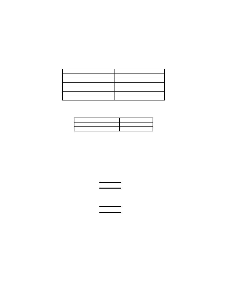
(g) Set the TI calculating counter controls (Channel 2) as follows:
Table 48-2 TI Calculating Counter Controls
CH2 DEC
5
CH2 C
14286
N
All 10 Period
0
CH2 Auto
depressed
CH2 x10
released
SAMPLE RATE (FAST)
1
TEST
released
(h) Set the tachometer tester controls as follows:
Table 48-3 Tachometer Tester Controls
Motor Direction
Forward
Set RPM
10%
Power
On
AEDATS Alignment See Calibration of Automatic Data Acquisition H345-1
(AEDATS II), or H355-7 (AEDATS IV) for FEDS Alignment requirements.
(i) Verify that the TI calculating counter and TI indicator indicate between 9.7% and 10.3%. Adjust
the TI indicator low (zero) potentiometers as necessary (R18 for digital and R20 for analog low
adjustments).
(k) Verify that the TI calculating counter and TI indicator indicate between 99.7% and 100.3%. Adjust
the TI indicator high (SPAN) potentiometer as necessary (R23 for digital and R29 for analog high
adjustments).
NOTE
Interaction may occur between TI indicator low and TI indicator high adjustments.
Repeat the previous five steps until no further adjustment is necessary.
NOTE
Ground E on TB 810 terminal # 17 if engine is not mounted (Disconnect E3 cable)
