
TB 1-4920-443-35
(d) Calculating counter, TI calculating counter and TI indicator should indicate between 9.7 and 10.3.
Adjust the TI indicator low (zero) potentiometer as necessary (R18 for digital and R20 for analog
low adjustments).
(f) Verify that the TI calculating counter and TI indicator indicate between 99.7% and 100.3%. Adjust
the TI indicator high (span) potentiometer as necessary (R23 for digital and R29 for analog high
adjustments).
NOTE
Interaction may occur between TI indicator low and TI indicator high adjustments.
Repeat the previous five steps until no further adjustment is necessary.
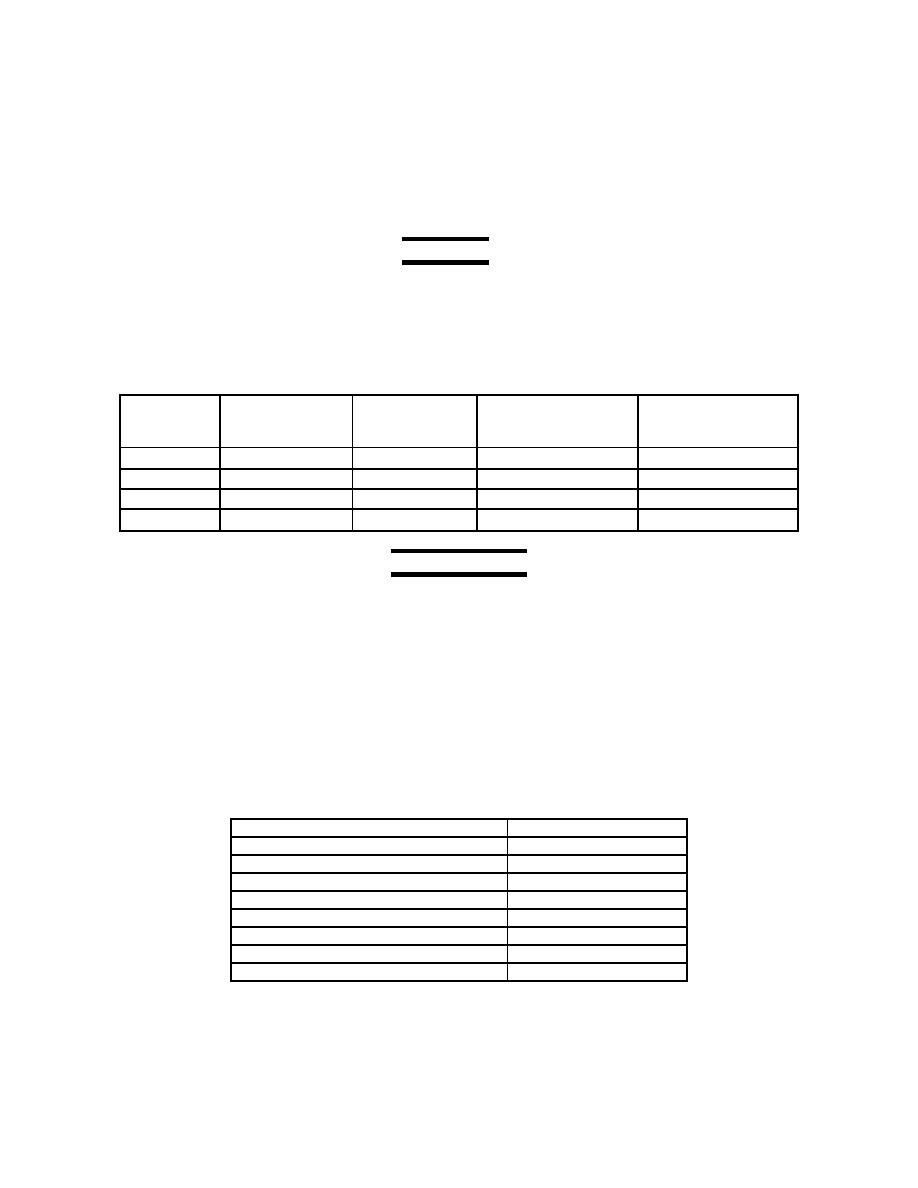
(g) Set oscillator to the speeds listed below. At each speed, verify that the TI calculating counter and
TI indicator indicates within the tolerance limits listed below. Record results.
Table 47-7 TI Calculating Counter vs. TI Indicator
Oscillator
TI Calculating
TI Indicator (%)
TI Indicator (%)
AEDATS (%)
(Hz)
Counter (%)
Digital 0.3%
Analog 0.3%
RPM2 1%
0.3%
854
1282
1709
2136
NOTE
For AEDATS II Channel names, refer to AEDATS (H345-1) Technical Manual, Appendix C and
for AEDATS IV Channel names, refer to AEDATS (H355-7) Technical Manual. Chapter 6.
AEDATS Alignment RPM2 - See Calibration of Automatic Data Acquisition H345-1
(AEDATS II), or H355-7 (AEDATS IV) for FEDS Alignment requirements.
48. Speed Measurement System
a. Performance Check (T53/T55/T63/T64 Mode)
(1) Power Turbine (N2) Speed Indicator
(a) Ensure that the system is in the T53/T55/T63/T64 mode (Reference FEDS operator's manual).
(b) Set the TI calculating counter controls (Channel) as follows:
Table 48-1 TI Calculating Counter Controls
All DEC switches to
6
All C switches to
11111
N
All 10 Periods
0
All AUTO buttons
depressed
All x10 buttons
released
CHANNEL 1 button
depressed
SAMPLE RATE (FAST)
1
TEST button
released
POWER button
depressed
