
TB 1-4920-443-35
47. Speed Measurement System
a. Performance Check (T700 Mode)
(1) Power Turbine (NP) Speed Indicator
(a) Ensure that the system is in the T700 mode (Reference FEDS operator's manual).
(b) Set the TI calculating counter controls (Channel 1) as follows:
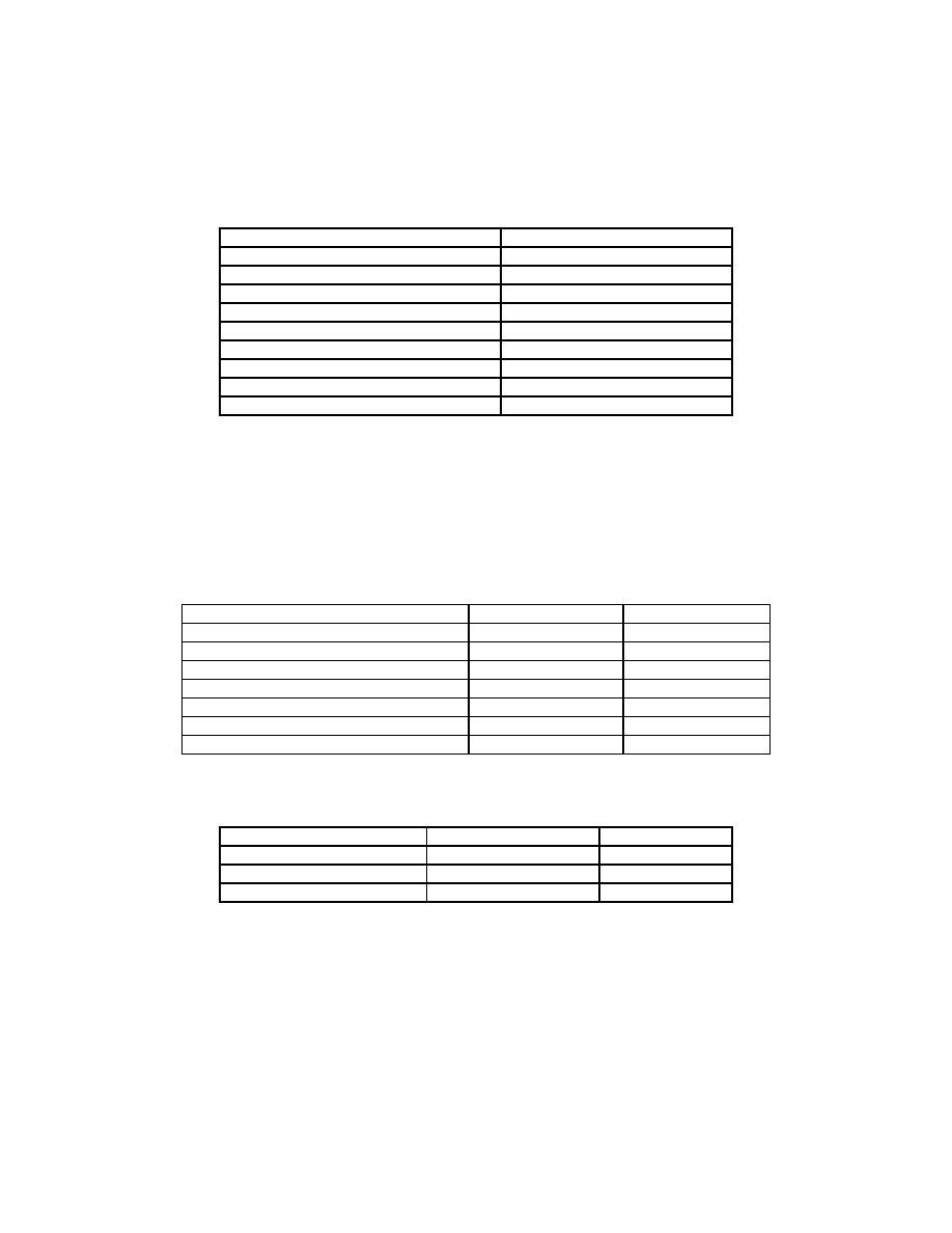
Table 47-1 TI Calculating Counter Controls
All DEC switches to
6
All C switches to
11111
N
All 10 Period
0
All AUTO buttons
depressed
All x10 buttons
released
CHANNEL ( 1 ) button
depressed
SAMPLE RATE (FAST) button
depressed
TEST button
depressed
POWER button
depressed
(c) Verify that the calculating counter indicates 011111. Depress the TI CH1 x10 selector IN, and
verify that the TI calculating counter indication is 111110. Depress the TI CH1 x10 selector OUT.
(d) Repeat the previous step for the remaining TI CH1 C thumb switch settings of 22222 through
99999 and 00000.
(e) Repeat the previous step and this step for the remaining TI calculating counter channels: CH2,
CH3, and CH4. Depress the TI calculating counter test selector Out.
(f) Connect the oscillator test set to pins 8 and 9 of E1.
(g) Set the TI calculating counter controls as follows:
Table 47-2 TI Calculating Counter Controls
T700/T701/T701C
401/401C
CH2 DEC
4
4
CH2 C
07502
07179
N
All 10 Periods
0
0
CH2 Auto
depressed
depressed
CH2 x10
depressed
depressed
SAMPLE RATE (FAST)
1
1
TEST
released
released
Table 47-3 Oscillator Settings
T700/T701/T701C
401/401C
Level
500 mV
500mV
Set Hz
133
139
Power
On
On
AEDATS Alignment See Calibration of Automatic Data Acquisition H345-1
(AEDATS II), or H355-7 (AEDATS IV) for FEDS Alignment requirements.
(i) Calculating counter, AEDATS and TI indicator should indicate between 9.7 and 10.3. Adjust TI
indicator low (zero) potentiometers as necessary (R18 for digital and R20 for analog low
adjustments).
(j) Set the oscillator to 1393.4 Hz at 1Vpp
