
TM 5-3610-253-14
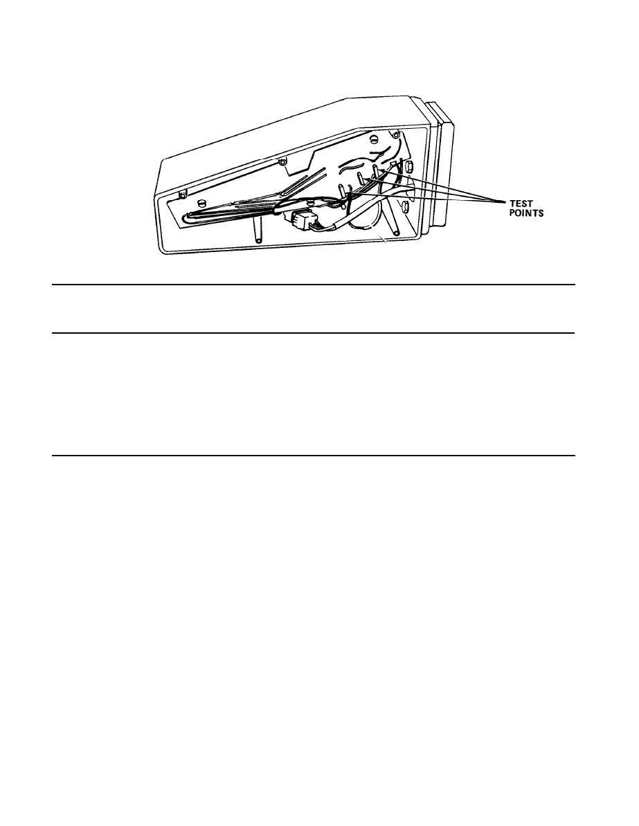
LIGHT BARRIER COLLECTOR SIGNALS AT INTERRUPTION
Light Ray
Associated Test
Expected
Interrupted
Point
Signal
1or4
G1
0.5 V dc min.
2or5
G2
0.5 V dc min.
3or6
G3
0.5 V dc min.
Average uninterrupted voltage level should be as close to zero volts as possible
with 0.12 volts maximum.
e. Non-repeat circuits. Prevents knife from making more than one cut at a time,
or from cutting when light barrier is interrupted during a cut. The non-repeat
circuits are controlled by non-repeat relay d230 on standard control PC ST. If
relay d230 is not energized, a cut cannot be performed. Relay d230 is de-energized
during the upward motion of the knife. This de-energizes relays d230 a/b which will
turn off emitter lamps 2, 4, and 6 which will de-energize relay d37. Relay d230
can't be energized again until the cutting buttons are released. Once d230 is re-
energize, relay d37 then can be re-energized, if the light barrier is not broken.
f. Safety bolt assembly. Contains a safety bolt controlled by a solenoid. When
knife carrier is at top of its stroke, spring tension keeps the safety bolt pressed
outward under a plate on the knife carrier, preventing downward motion of the knife.
When solenoid is activated, it pulls the bolt back to allow a cut. When the knife
reaches the bottom of its stroke, the solenoid de-energizes and the bolt moves
against the back of the knife carrier. Once the knife carrier reaches the top, the
safety bolt is then free to extend fully and prevent the knife from making a cut.
When the bolt is drawn back, it will activate a proximity switch (b.SB). This
switch (b.SB) ensures that the bolt is replaced under the carrier after the cut. To
re-activate the safety bolt, the cutting buttons must be released and then pressed
again.
5-18
