TM 5-3610-253-14
Controls movement of backgauge, via a control knob,
(4) Backgauge controls.
limit switches, and a button. The control knob is mounted on one end of a metal
rod, with a toothed gear on the other end, and a trip dog cam mounted on middle of
rod. Two microswitches are mounted next to trip dog cam. Pushing the control rod
in will control the contacts on one switch (b18), and pulling it out will control
the contacts of the other switch (b10). Pushing the control knob in activates
switch (b18) which disengages the backgauge brake. The toothed gear engages a
toothed gear on the table spindle. This allows turning of the knob to finely adjust
the position of the backgauge. Pulling the control knob out activates switch (b10)
which allows the backgauge motor to turn in a direction that allows the backgauge to
move forward. Pressing the button in the middle of the control knob activates
switch (b14). Activating this switch allows the backgauge motor to turn in a
direction that allows the backgauge to move back.
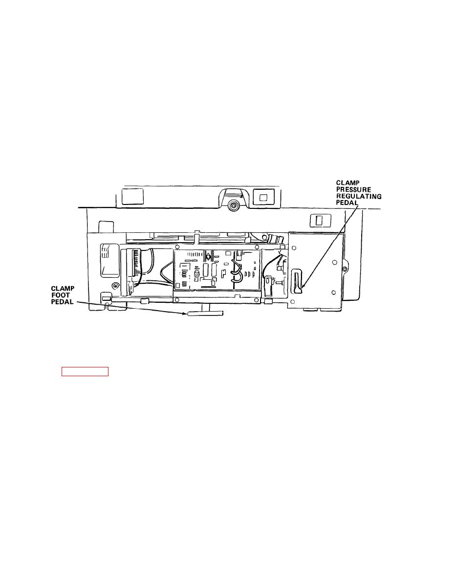
(5) Clamp foot pedal . Controls operation of the clamp. When pressed, trip
dogs mounted on pedal axle close clamp pedal switch (b309) and press in clamp
control valve in hydraulic system control block. This initiates sequences of opera-
tion (Table 5-3) in the electronics and hydraulics that control operation of the
clamp when using the foot pedal.
(6) Clamp pressure regulating pedal.
Used to adjust the pressure of the
clamp.
d. Light barrier. Safety system, when activated, directly controls operation of
the knife. The light barrier consists of two halves:
5-16

