
TM 5-3610-253-14
(1) Main drive motor. Provides power to the hydraulic pump, and the hydrau-
lic clutch and gear assembly, via three' pulleys and two V-belts (the clutch and gear
assembly drive the knife). It is controlled directly by the main power switch
on the control panel. It continues to run as long as the main power switch is in
the "I" (on) position. The main motor has a high stalling torque, so that when
materials have to be cut, rpm of the motor will drop but the knife will be pulled
through the material without fluctuating. An overload relay, located under the
cutting table, directly above the right pillar, protects the main drive motor from
an overload.
(2) Backgauge motor. Provides power to the backgauge carrier via a pair of
pulleys and a V-belt. Operation and the direction of rotation of motor is control-
led by a pair of contractors c12 and c15 on standard control PC ST, limit switches
mounted along the table bed, and backgauge controls. Power is input from the
control transformer. When not in use, the motor is off. When contactor c12 is
energized by the backgauge control circuit, the N.O. contacts close and the motor
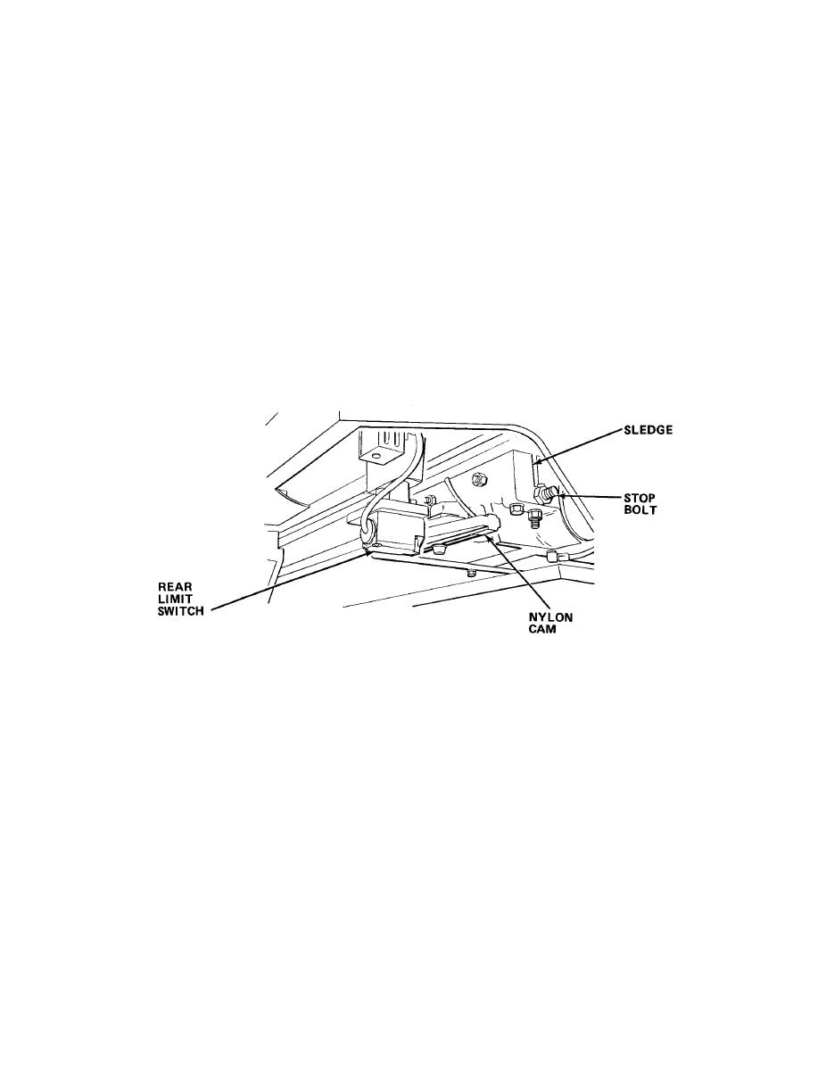
runs forward. If c15 is energized, the motor runs backward. Limit switches mounted
along the table bed where the backgauge runs limits the distance the backgauge can
travel in either direction. The switches are activated by a pair of nylon trip dog
cams that ride on the sledge.
When activated, switches cut power to motor. Switch b13 limits (i.e., is activated
by) backward travel. Two switches, b8 and b9, limit forward travel. The first of
these switches, b8, can only cut power to motor if false clamp has been removed from
its mount, activating limit switch b6 on which it rests. Switch b8 is used to limit
backgauge travel shorter than normal to provide the extra space needed to mount the
false clamp. The backgauge motor is protected by an overload relay. The relay is
located under the backgauge table on the back of the support brace.
5-21
