
TM 5-3610-253-14
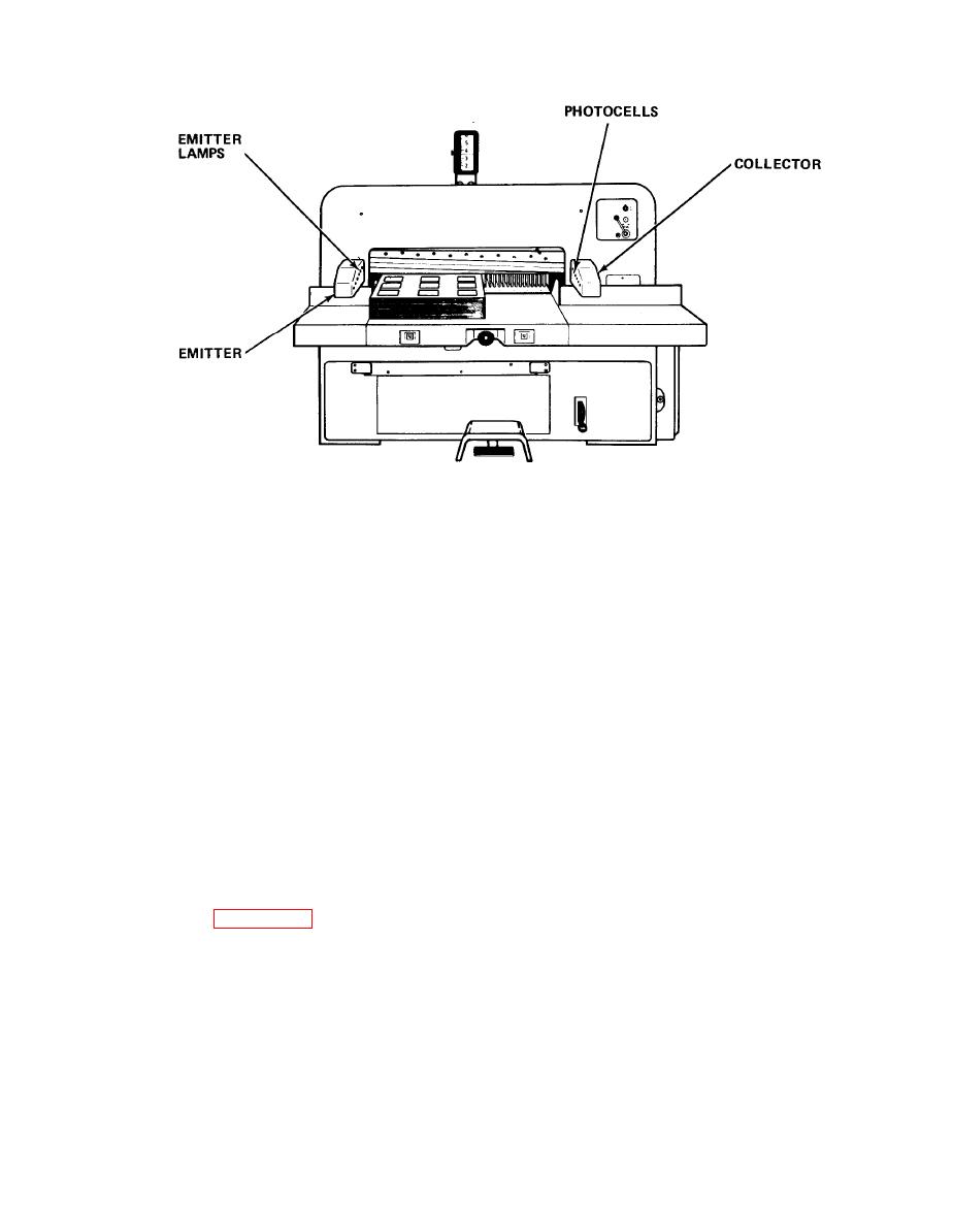
(1) Emitter. Contains an array of six lamps and lenses. A lens is mounted
in front of each lamp to focus the light transmitted by the lamp. The transmitted
light is directed toward collector across cutting area of the table. The lamps are
mounted on adjustable spring bases so the intensity and direction of transmitted
light can be adjusted. A relay board (LSL) is mounted in the housing to control the
operation of the emitter lamps.
(2) Collector. Contains a set of photocells mounted on the photo element
board (LSF), and lenses, arranged opposite transmitting lamps. The photocells
collect transmitted light, focused by lenses, to create sufficient voltage to cause
a transistor stage on light barrier PC card 9 to become conductive towards a O-logic
voltage level. The photocells are switched in pairs. A separate signal lamp in
the collector indicates when all the photocells are receiving light. If operator
reaches across table toward knife, one or more light beams are interrupted, causing
the voltage level in the collector cells to raise. This results in a logic-1
voltage (2.5 V dc) in card 9 (test point 9R4), which de-energizes relay d37 powering
the signal lamp and causes the hydraulic clutch on the main drive motor to disen-
gage, engaging the spring-activated brake and stopping the knife during downward
motion. Before each cut is performed, the condition of light barrier collector
automatically is tested to ensure no beams are being interrupted. The photo element
board has three test points, G1, G2 and G3, used to check voltage output of
photocells. Table 5-1 shows voltage values that should be received if a light beam
is interrupted.
5-17
