
TB 1-4920-443-35
(10)Depress and release the TI Limit Control RESET switch.
(11)Depress the TI Limit Control POWER OFF switch.
41. Speed Limit Control - Over speed Power Section No. 1 T53/T55/T63/T64 MODE
a. Performance Check
(1) Ensure that the system is in the T53/T55/T63 mode with the Indicator Panel (20090829-1) installed.
(Reference FEDS operator's manual).
(2) Turn on power to T53/T55/T63/T64 Performance Monitoring System. Allow system to conduct BIT. If
BIT fails refer to system troubleshooting. Send System to depot for repairs, if necessary.
(3) Depress the MODE switch 3 times. The test mode should be in the 3333 Hz position.
(4) Verify that the TI Limit Control indicator reads 3333 3Hz. Verify frequency on back panel (pins 1 and
2) is 3333 3Hz.
(5) Adjust thumbwheel setting to 3333 and verify the 100% alarm activates. Adjust thumbwheel setting to
3700 3 and verify the 90% alarm is activated.
(6) Adjust thumbwheel setting to 3800 3 and verify that all alarms are off.
(7) If any of steps 3-6 fail, send the Limit control Panel to depot for repair.
42. Hydraulic Pressure Measurement System
a. Performance Check (T700 Mode)
Ensure that the system is in the T700/T701/T701C mode. (See Engine Test Configuration). Align
AEDATS concurrently with the vertical scale indicators.
(1) MT16:
0-50 PSIG (T700)
Using the pressure calibrator, apply the following pressures to MT16 and record the results.
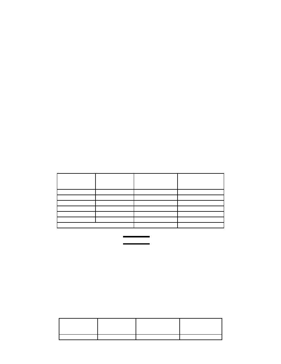
Table 42-1 MT16 Alignment
Target
Calibrator
Vertical Scale
AEDATS
Pressure (psig)
Pressure (psig) Bottom Row #11
Pdyn_sup ( 1 PSI)
Indicator ( 2 PSI)
VENT
10
20
30
40
50
RCAL=
NOTE
AEDATS channel names for all engines is Pdyn_sup.
AEDATS Alignment MT16 - See Calibration of Automatic Data Acquisition
H345-1 (AEDATS II), or H355-7 (AEDATS IV) for FEDS Alignment requirements.
(2) MT17:
0-150 PSIG (T700)
Use pressure calibrator to apply the following pressures to MT17A. Vent MT17B. Record the results.
Table 42-2 MT17 Alignment
Calibrator
Vertical Scale
Target
AEDATS
Pressure (psig)
Pressure (psig)
Top Row #5
BSUMP ( 1 PSI )
Indicator ( 2 PSI)
VENT
