
TB 1-4920-443-35
NOTE
To gain access to the TI Temperature Indicator alignment controls, remove the two screws
from the sides of the front panel and remove the panel. The two potentiometers are visible
at the upper left of the display. Potentiometer R44 (Front Panel ZERO) controls the ice
point indication and R45 (SPAN) controls the positive (+) full scale indication.
(6) Adjust the thermocouple calibrator controls to a temperature of 1000 F.
(7) Verify that the temperature indicator reads between 999 to 1001 F. Adjust the indicator positive (+)
full-scale adjustments. Repeat the previous four steps until no further adjustment is necessary.
NOTE
Interaction may occur between the TI temperature indicator ice point and positive (+) full-
scale adjustments. Repeat the previous four steps until no further adjustment is
necessary.
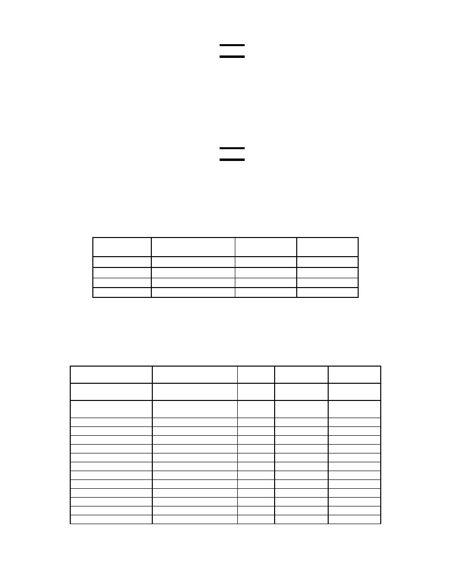
(8) Adjust the thermocouple calibrator controls to obtain the temperature values listed below. At each
temperature setting, verify that the TI indicated temperature is within the tolerance limits.
(9) Do not calibrate AEDATS EODT at this time, as it will be calibrated in the next section.
Table 27-1 TI Temperature Indication
Thermocouple DORIC and AEDATS
DORIC
AEDATS EODT
Calibrator (F) Tolerance Limits ( 1) Actual Reading Actual Reading
32
31 to 33
100
99 to 101
200
199 to 201
300
299 to 301
NOTE: AEDATS Alignment/Check for this channel will be completed in the next section.
28. Type-J Thermocouple Alignment T700 Trailer
a. Performance Check
(1) In this section we will align the Type-J thermocouple channels monitoring the T700 engine tests.
These channels are listed in the table below.
Table 28-1 T700 Type-J Thermocouple Channels
Channel Name
Connector
Doric
AEDATS II/IV
Temperature
Label
Channel
Channel
Range
0-300 oF
Engine Lube
P56 or
1
BSUMP
Discharge Temp
Eng Lube Disch Temp
0-300 oF
Engine Oil
P57 (BSUMP)
2
J02
Scav. Temp.
0-120 oF
Inlet Air Temp
P58
3
T21
0-120 oF
Inlet Air Temp
P59
4
T22
0-120 oF
Inlet Air Temp
P68
5
T23
0-120 oF
Inlet Air Temp
P92
6
T24
0-120 oF
Inlet Air Temp
P101
27
T25
0-120 oF
Inlet Air Temp
P102
28
T26
0-120 oF
Inlet Air Temp
P103
29
T27
0-120 oF
Inlet Air Temp
P104
30
T28
0-300 oF
Dyno Lube Tank Temp J20 of dyno
7
Tdyn_tnk
0-300 oF
Tdyn_fwd
Dyno Lube Out Fwd
J21 of dyno
8
0-300 oF
Tdyn_aft
Dyno Lube Out Aft
J22 of dyno
9
0-300 oF
TDyno F/A
J20, J23 & J24 of dyno
none
Tdyn_FA
