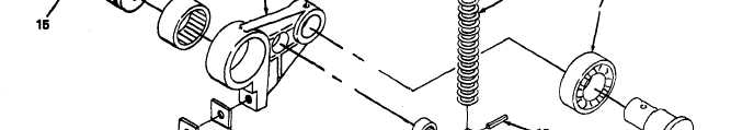
Figure 2-175.
TM 5-3610-286-20
2-69. Impression Cylinder Control Mechanism (cont).
(3) Impression ON cam assembly.
(a) Replace needle bushing (1, figure 2-175) in roller lever (2).
(b) Position shims (3) and plate (4) on roller lever (2) and replace socket-head screw (5).
(c) Replace roller shaft (6) and ball bearing (7) on roller lever (2) and replace spring
tension pin (8).
(d) Replace needle bushing (9) in rod head (10).
(e) Replace rod head (10) on spring rod (11) and replace spring tension pin (12).
(f) Replace compression spring (13) on spring rod (11).
(g) position spring rod assembly on roller lever (2) and replace pin (14).
(h) Slide roller lever (2) on drive shaft (15) and assemble key (16) in shaft.
2-374