Figure 2-179.
TM 5-3610-286-20
2-69.
Impression Cylinder Control Mechanism (cont).
(2) Impression cylinder control mechanism.
(a)
(b)
(c)
(d)
(e)
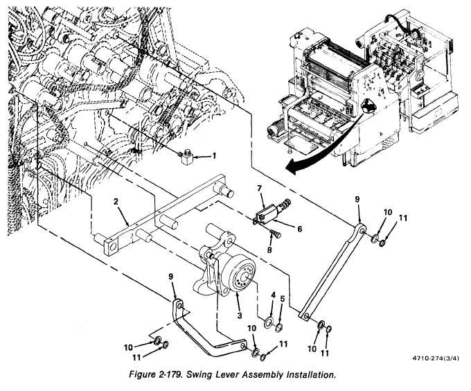
Replace stop (1, figure 2-179) in side of press.
Position pull rod (2) in swing lever assembly and install swing lever assembly (3) on
bearing bolt in side of press.
Install washer (4) and retaining ring (5).
Position switch (6) and switch bracket (7) on press and install two hex-head
screws (8).
Install two pull rods (9), four flat washers (10), and four retaining rings (11).
2-378