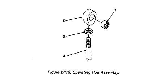
Figure 2-173.
TM 5-3610-286-20
2-69.
Impression Cylinder Control Mechanism (cont).
e. Assembly.
(1) Operating rod assembly. (figure 2-173)
(a) Replace needle bushing (1) in rod head (2).
(b) Replace nut (3) and rod head (2) on operating rod (4).
(2) Swing lever assembly.
(a) Replace screw (1, figure 2-174) and nut (2) on stop (3).
(b) Replace three straight pins (4) in pull rod (5) and replace three spring tension
pins (6).
(c) Replace stop bolt (7) in control lever (8) and replace spring tension pin (9).
(d) Replace shouldered stud (10) in control lever (8).
(e) Replace stud (11) and compression spring (12) in control lever (8) and swing
lever (13).
(f) Replace spring tension pin (14) in control lever (8).
(g) Replace spring tension pin (15) in handle rod support bolt (16).
2-372

