Figure 2-113.
TM 5-3610-286-20
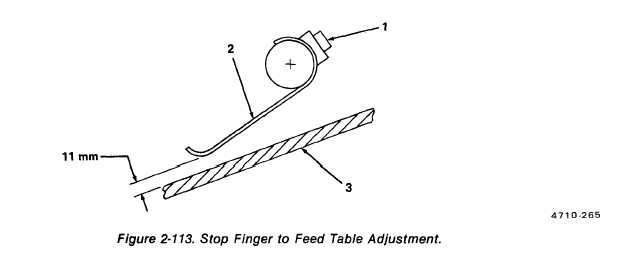
(b) Stop finger clearance. (figure 2-113)
1 Loosen socket-head screws (1) on each stop finger (2).
2 Adjust the stop fingers for 11 mm clearance to the feed table (3).
3 Tighten socket-head screws (1).
NOTE
FOLLOW-ON MAINTENANCE:
Install pull side lay assembly (para. 2-49).
2-265