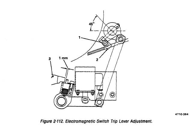
Figure 2-112.
TM 5-3610-286-20
2-50.
Pull Rail Assembly (cont).
a. Adjust.
(1) Pull rail height.
(a) Pull rails have to be set flush with feed table or exactly 0.05 mm above feed table.
(b) Adjust height by placing or removing shims under guide rails (see figure 2-111 and
installation procedure b). Shims sizes are as follows: 0.025, .05, and .10.
(c) Set height of support bars, placing or removing shims under support bars (see figure
110 and repair procedure c). Magnet plates on support bars must be exactly flush
with feed table.
(2) Stop finger to feed table clearance.
(a) Electromagnetic switch trip lever. (figure 2-112)
1 With stop fingers disengaged, loosen nut (1) on stop angle (2).
2 Adjust stop angle (2) so that, through linkage, there is a 1 mm gap at the electro-
magnetic switch trip lever (3).
2-264

