
TB 1-4920-443-35
60. T700 Load Demand Spindle Position
a. Performance Check
Note: AEDATS Alignment See Calibration of Automatic Data Acquisition H355-7 (AEDATS
IV) for FEDS Alignment requirements.
(1) The TI will request the channel name. Enter LDS, then press the return key.
(2) The TI AEDATS II screen will request the first calibration point. Do not enter a value at this time. (The
TI AEDATS II screen will display an input range of 0.0 to 12.0 VDC and an output range of -45 to
105.0).
(3) Disconnect TI plug P51.
(4) Connect the Voltage Calibrator to the TI plug P51, pins A (+) and B (-), observing polarity.
(5) Set Voltage Calibrator output controls for 0.00 VDC.
(6) Enter 0 as the first TI AEDATS II Alignment point, then press the return key. After 0 is entered, the TI
AEDATS II screen will request the second calibration point. Do not enter a value at this time.
(7) Set the vertical scale ZERO control for a TI indication of 0 deg.
(8) Set the Voltage Calibrator output controls for 12.00 VDC.
(9) Set the vertical scale SPAN control for a TI indication of 105 deg.
(10) Enter 105 as the second AEDATS II Alignment point, then press the return key. After 105 is entered,
the TI AEDATS II screen will request satisfactory Y/N? Do not make a selection at this time.
(11) Set Voltage Calibrator output controls for the values listed.
(12) The TI AEDATS II screen and the Vertical Scale must indicate within the corresponding values listed.
(13) Record results.
(14) After the last test point, enter Y to satisfy the AEDATS II screen request for satisfactory Y/N? then
press the return key.
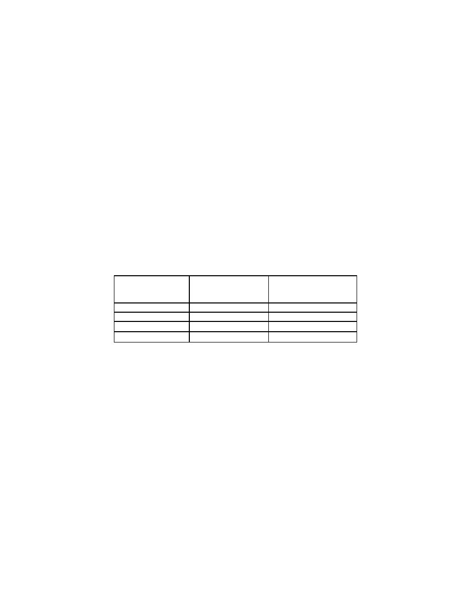
Table 60-1 LDS
Voltage Input
AEDATS 4
Vertical Scale
(VDC)
LDS
Bottom Row #2
(0.5 deg)
Indicator (1.0 deg)
0 (-45 deg)
4 (05 deg)
8 (55 deg)
12 (105 deg)
(15)Set the Voltage Calibrator for minimum output.
(16)Disconnect the Voltage Calibrator from TI plug P51.
(17)Reconnect TI plug P51.
