
TB 1-4920-443-35
58. T53/T55/T63/T64 Fault Light Panel
a. T53/T55/T63/T64
(1) Ensure that the system is in the T53/T55/T63/T64 mode (Reference FEDS operator's manual). All
references to the dyno in T53/T55/T63/T64 sections are to the large air dyno on the T53/T55/T63/T64
Test Trailer.
b. Dyno Supply Low Pressure
(1) Locate pressure switch 19PS on the Engine Test Trailer. Disconnect the existing hose and attach the
High Pressure Calibrator. The Dyno Supply indicator should be illuminated (with 0 psig applied).
(2) Apply pressure gradually from zero psig through 15 psig. The Dyno Supply indicator should go out at
approximately 10 2 psig.
(3) Remove the test equipment and reconnect the hose removed in step 1 above.
c. Main Valve Closed, Valve Select, and Fuel Boost Pressure
(1) Energize the Fuel Pump. The Main Valve Closed indicator should go out, the Valve Select indicator
should light ARMY, and the Fuel Boost Pressure should go out for ARMY.
NOTE
Replace ARMY with T64 for T64 test systems.
(2) De-energize the Fuel Pump.
d. Chip Detector
(1) Using any of the following Flight Harnesses:
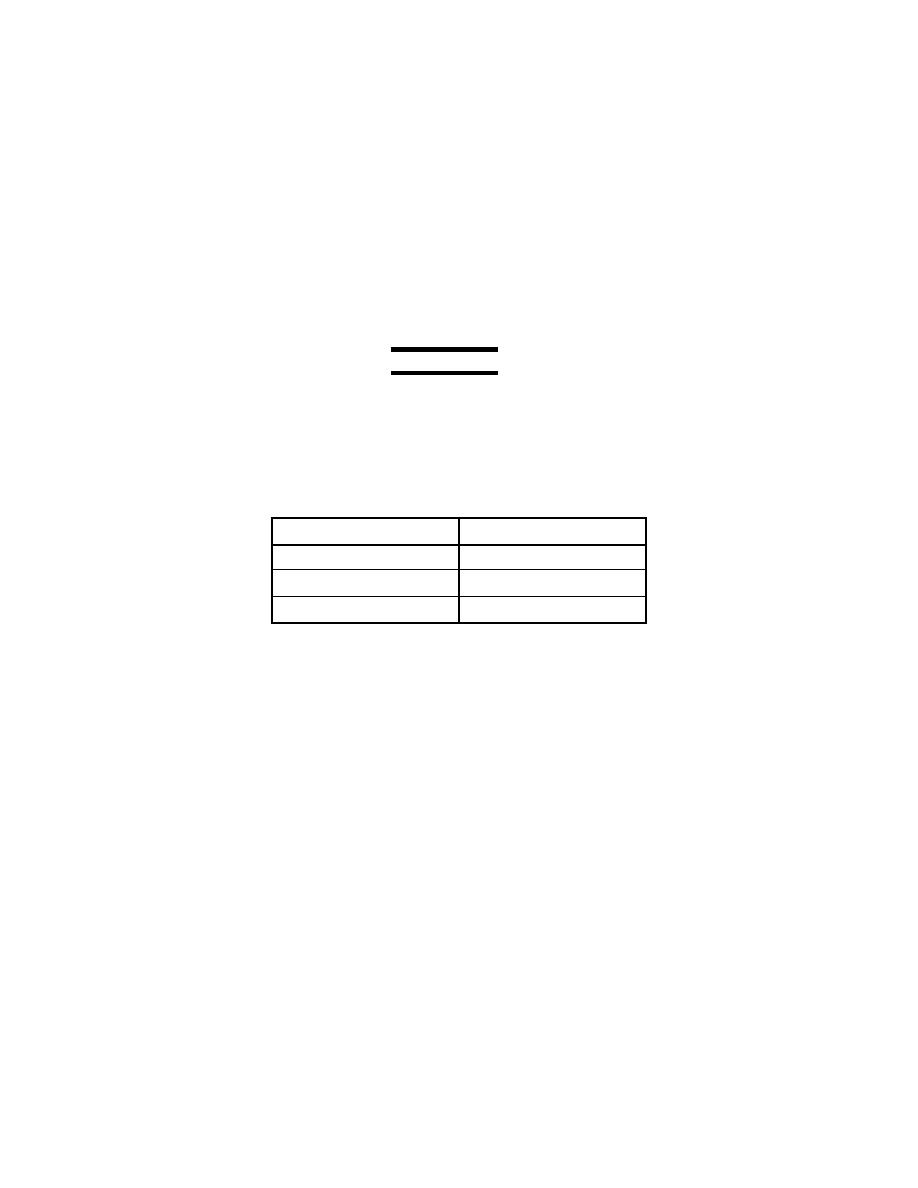
Table 58-1 Flight Harnesses
20090775 1
T53
20090776 1
T55
20090777 1
T63
20090950 1
T64
(2) Touch the chip detector lead to ground. The chip detector indicator should light.
e. Dynolube Filter delta-P
(1) The Lube Filter Bypass indicator in the Air Dyno section of the Fault Light panel should be
extinguished. Locate pressure switch 18PS on the Test Trailer and disconnect the existing hose.
(2) Connect the High Pressure Calibrator to pressure switch 18PS. Slowly increase the pressure from
zero to 15 psig. At approximately 10 1 psig the Lube Filter Bypass indicator should light.
(3) Remove all test equipment and reconnect the hose in step 1 above. Leak check this connection.
f.
Dynolube Tank Low Level
(1) The Low Oil Level indicator will light when the dynolube tank is low on oil. This can be observed when
changing the oil on the dynolube system.
(2) The above condition can be simulated by jumping pins F and G on connector J103 located on the
Auxiliary J-box, 20090707-1.
g. Dyno Low Oil Pressure Forward
(1) The Low Oil Press Fwd 5PS/17PS indicator should be illuminated. Disconnect the hose connected to
pressure switch 17PS on the J-box.
(2) Connect the High Pressure Calibrator to pressure switch 17PS on the J-box. Apply a pressure of 15
psig, the Low Oil Press Fwd 5PS/17PS indicator should go out.
(3) Slowly decrease the pressure. At approximately 10.5 .5 psig, on decreasing pressure, the Low Oil
Press Fwd 5PS/17PS indicator should light.
(4) Disconnect the test equipment and reconnect the hose removed in step 1 above. Leak check this
connection.
h. Oil Filter delta-P
