
TB 1-4920-443-35
b. Performance Check (AEDATS II Only)
(1) Ensure that the FEDS system is in the T53/T55/T63 mode (Reference FEDS operator's manual).
(2) Connect the decade resistor to pins N and K of the T55 Flight harness, or N and P of the T53 Flight
Harness.
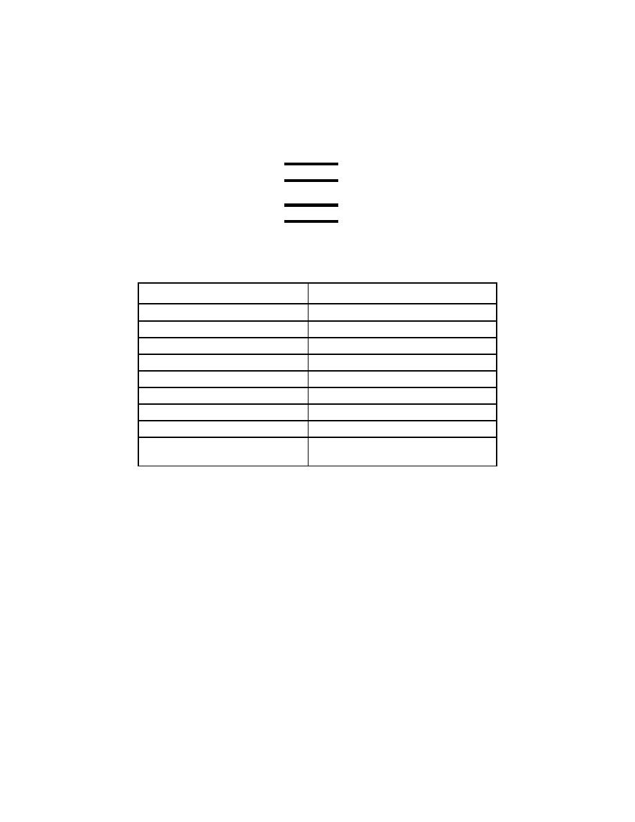
(3) Adjust the decade resistor to obtain the TI engine oil inlet temperature gage indications listed below.
At each indication verify that the decade resistor indicates within the tolerance limits listed. Record
results.
NOTE
Turn switch to 712 on signal conditioning chassis.
NOTE
The 0-400 temperature gauge will read approximately 20 degrees high because of
resistance in the wiring from the control cab to the engine
Table 56-2 TI Temperature Gage Indications
Decade Resistor (ohms)
TI Temperature Gage Indication (F)
90.34 to 90.42 Ω
(32F) 10
97.27 to 97.35 Ω
(68F) 10
104.56 to 104.64 Ω
(104F) 10
111.78 to 112.78 Ω
(140F) 10
119.86 to 120.86 Ω
(176F) 10
128.35 to 129.35 Ω
(212F) 10
141.80 to 143.00 Ω
(266F) 10
151.31 to 152.51 Ω
(302F) 10
176.95 to 178.95 Ω
(392 F)
10
NOTE: For use with AEDATS II Configuration only
66
