
ARMY TM 9-6675-349-12&P
MARINE CORPS TM 11039A-12&P
OPERATING INSTRUCTIONS
SECTION I. CONTROLS AND INSTRUMENTS
3-1. Damage from Improper Setting.
No combination of control settings will cause damage to the equipment or create a hazard to personnel.
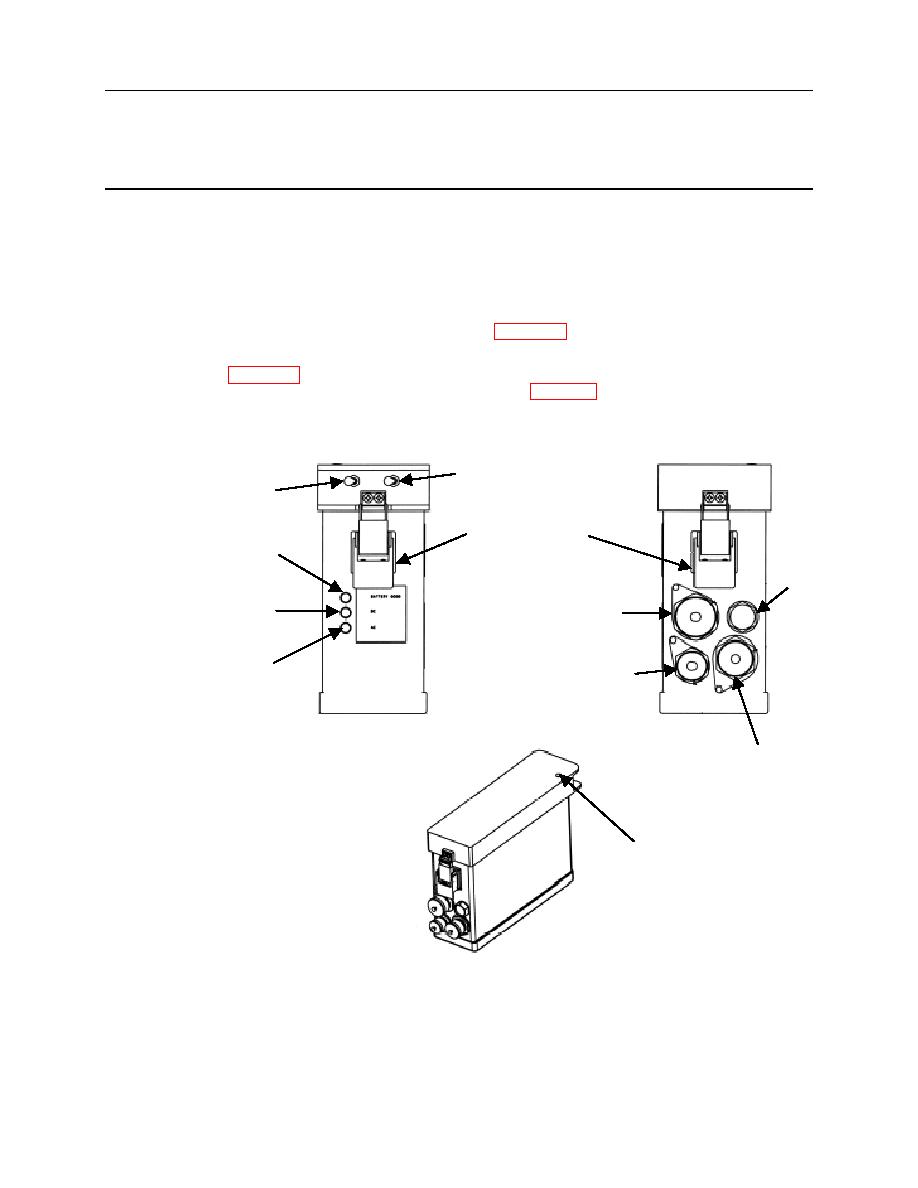
3-2. Operator/Crew Controls, Indicators, and Connectors.
IPADS controls, indicators, and connectors are illustrated in figures 3-1 through 3-5.
a.
BCU. The BCU has switches to control input power (DC INPUT) and output power (Output) to the CDU
and CPNU, figures 3-1 and 3-7. There are indicators for input power, battery charge state and battery
temperature, and connectors for both input and output power, figure 3-1.
DC Input
Output
BCU Cover Latch
Battery Good
Indicator
Vent
External DC
24 VDC Power
Power Indicator
Input Connector
External AC
Power Output Connector
Power Indicator
(to CPNU and CDU)
AC Power
Input
Connector
Battery Temperature
Indicator
