TM 5-3610-286-10
2-7.
OPERATING PROCEDURES
b.
Prepare Paper Cycle
(CONT)
(Cont)
(k) Set suction air valve, located under feeder table, to fourth
position from left.
(l) Set front lay
Printing Press.
height adjustment screw to zero on both sides of
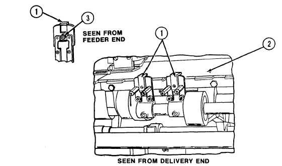
(m) Take Printing Press off safe and inch until front lays (1) are
in their lowest position over feeder table.
(n) Put Printing Press on safe.
Insert 0.10 mm feeler gage between
front lays (1) and feeder table (2).
If feeler gage is snug in front lay,
proceed to paragraph 2-7b (5).
If not, proceed to step (o).
(o) Take Printing Press off safe and inch until socket head screw
(3) is accessible.
Loosen socket head screw (3).
(p) put Printing Press on safe.
Lift front lay (1) high enough to
allow feeler gage to be inserted.
(q) Finger tighten socket head screw (3).
(r) Take Printing Press off safe and inch until front lays are
again in their lowest position.
2-42