TM 5-3610-253-14
d.
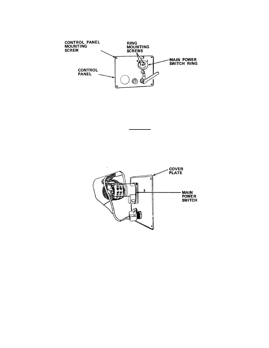
Remove main power switch knob.
(1) Remove main power switch ring.
(2) Remove four screws holding control panel in place and remove cover
CAUTION
Main control panel is connected to paper cutter via a rod attached to
knife change lever. Panel cannot be pulled away from paper cutter more
than a few inches without damage to rod.
(3)
Pull panel a few inches away from paper cutter so that rear of
main power switch is visible.
(4)
Tag and disconnect wires.
Remove two mounting screws, nuts, and lockwashers, and remove
(5)
defective switch.
Insert new switch and secure with screws, nuts and lockwashers.
(6)
(7)
Reinstall cover plate and main power switch ring.
5-175

