TM 5-3610-253-14
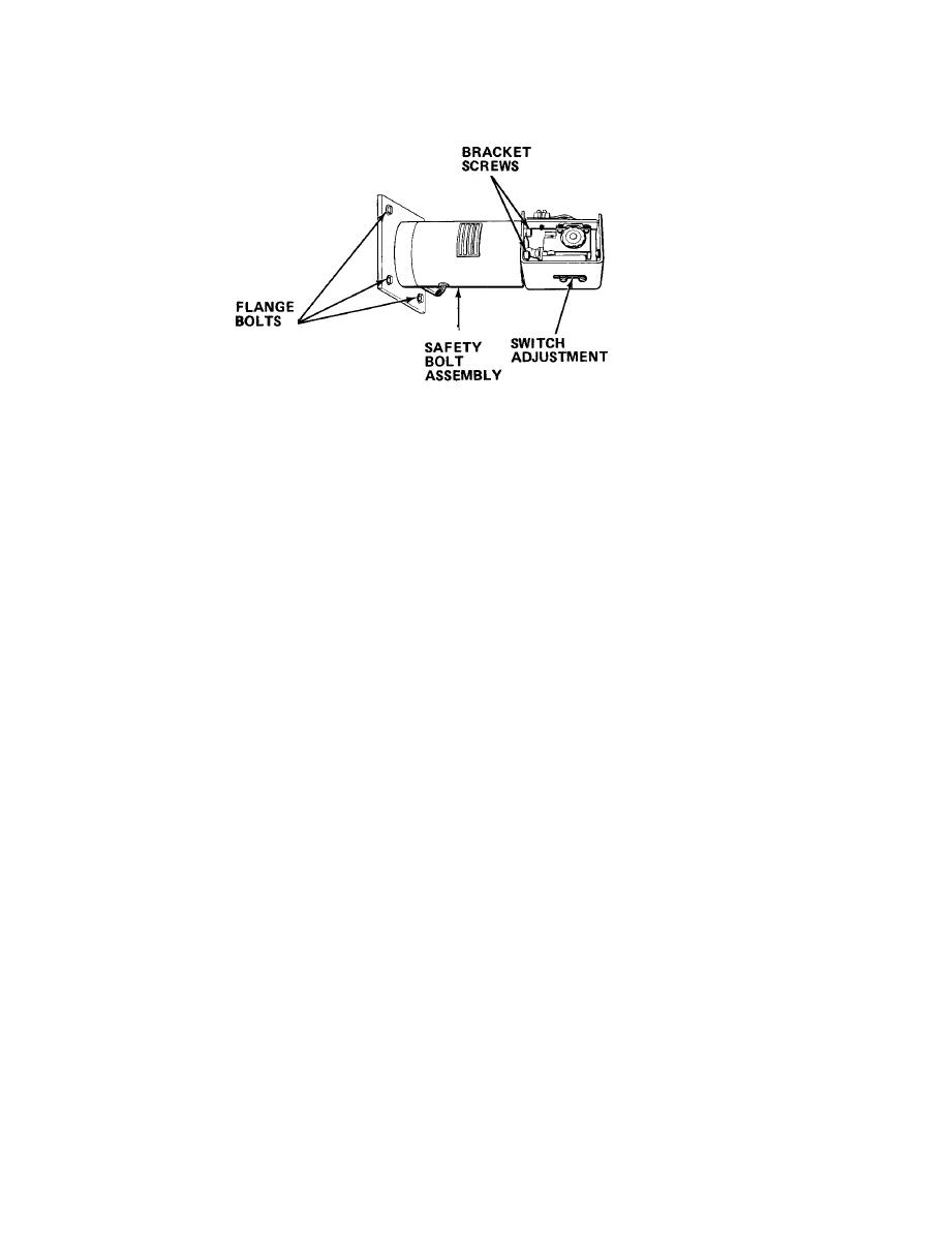
Loosen adjustment screws and slide switch back to allow access to
d.
bracket screws.
Remove screws and bracket.
e.
f.
Remove flange bolts and safety bolt assembly.
Install new safety bolt assembly and secure with flange bolts.
g.
Reinstall bracket and secure with screws.
h.
i.
Reconnect solenoid wiring to terminal block.
Turn on power.
j.
(1) Using operator key, unlock safety lock.
(2) Turn main power switch to I position.
(3) Press control power on switch.
Momentarily press the cutting buttons to activate the safety bolt
k.
solenoid.
Loosen switch adjustment screws. Adjust position of switch so that
l.
solenoid rod depresses switch plunger and activates switch.
m.
Tighten adjustment screws.
n.
Press both cutting buttons and complete the cut cycle.
Turn main power switch to 0 position.
o.
Reinstall safety bolt cover.
p.
5-179

