TM 11-5855-261-23
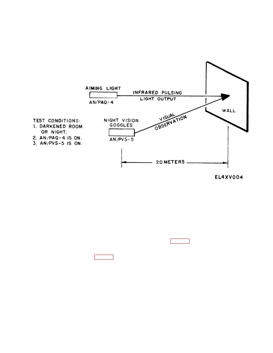
Figure 4-1. Infrared aiming light functional test set-up.
ates satisfactorily, the low temperature adapter is defec-
away from the light. Use Night Vision Goggles
tive and must be replaced. If the adapter electrical cable
AN/PVS-5 or -5A and observe the light spot. For pro-
is broken or electrical contacts are badly corroded,
per operation, a sharp, well-defined circular spot of
replace the adapter. Dirt may be removed from the elec-
pulsing light should appear. The pulsing spot should be
trical contacts with a clean, dry, lint-free cloth.
approximately 6.5 centimeters (2.5 inches) in diameter.
The aiming light must emit a pulsing light beam to
d. Battery Replacement. Remove the aiming light bat-
teries and replace them with new batteries know to be
operate properly. Also, proper operation can be observed
fully charged (para 4-7b. ). Perform functional test of
by looking directly into the aiming light lens and seeing
b.(2) above. If the aiming light is operable, reinstall the
a dim, red, pulsing spot,
switch assembly, check the unit, and return it to service.
(3) If continuity is not verified in the switch as-
If the aiming light is not operable, continue trouble-
sembly, replace it with a spare (para 4-7d. ). After
shooting.
switch replacement, check the aiming light and, if
operable, return to service. If continuity is verified,
4-6. Direct Support Troubleshooting Pro-
continue troubleshooting,
cedures
(4) If electrical circuit continuity is not verified,
continue troubleshooting. If it is verified, reas-
a. The laser diode assembly and laser electronics
semble the unit, check it out, and return to service.
assembly are the only replaceable electronic assemblies
c. Low Temperature Adapter Test. If the aiming light
in the aiming light. These units may be removed, or ex-
does not operate with the low temperature adapter, re-
posed for testing, by following procedures in Section III
place the batteries with pretested batteries and recheck
of this chapter.
pretested batteries in aiming light battery case and check
b. The following pass (P), fail (F) procedures (fig.4-2)
the normal mode of operation. If the aiming light oper-
should be performed for fault isolation to these com-
4-2


