TM 11-5855-261-23
screws that hold the switch (fig. 4-3), Remove
(3) Tighten the backup cap screw with a standard
screws and four flat washers.
1/4-inch screwdriver.
(2) Lift the switch plate out and fold it over for ac-
g. Refractive Lens Removal.
cess to two switch lead terminals.
(1) Unscrew and remove scattershield.
(3) Remove two screws that hold the switch leads
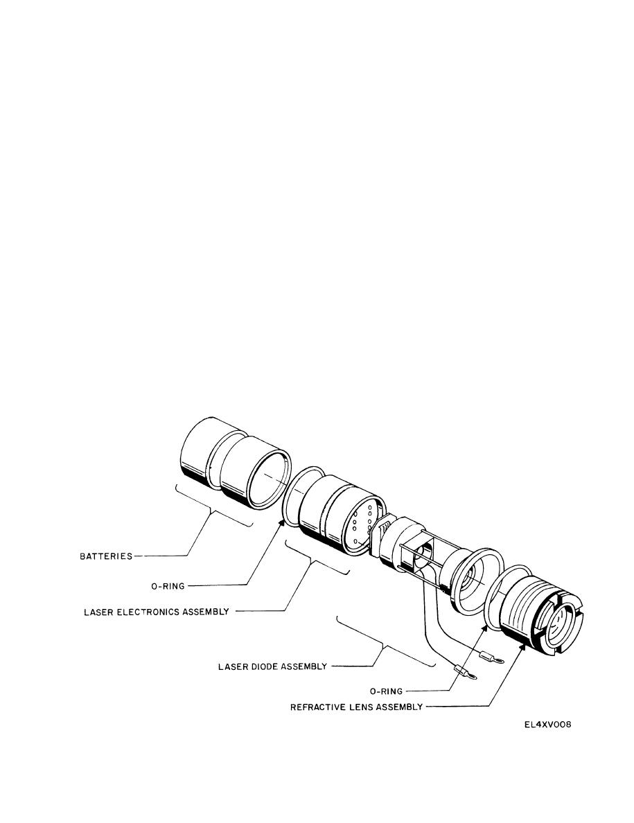
(2) Unscrew the lens assembly (fig. 4-5) using a
and note which color wire goes to each terminal.
special spanner wrench (table B-1, item 1).
(3) Remove the lens after the threaded portion
(4) Remove the Switch.
clears the housing.
(5) Unscrew two backup cap screws (fig. 4-4) using
h. Refractive Lens Replacement.
a standard 1/4-inch screwdriver.
(1) Lubricate (MIL-S-8660 or equivalent) the re-
(6) Remove the backup cap screw with O-rings,
fractive lens O-ring (fig. 4-5)
springs, and caps.
(2) Clean both sides of the lens assembly with lens
(7) Using an 8-inch adjustable wrench unscrew and
paper. Lens paper may be dampened with clean
remove the azimuth adjuster.
water if required.
(8) Repeat step (7) with the elevation adjuster.
(3) Insert the O-ring and lens assembly with the un-
(9) Unscrew the allen head cap screw (fig. 4-6) that
threaded portion first.
holds the electronics assembly using a 1/8-inch
(4) Screw in the lens assembly and tighten with the
allen wrench.
special spanner wrench (table B 1, item 1).
(10) Unscrew and remove the scattershield.
(5) Replace the scattershield (fig. 4-3).
(11) Unscrew the lens assembly (fig. 4-5) using the
CAUTION
spanner wrench.
To avoid cross-threading, insert and turn the
CAUTION
scattershield counterclockwise a half turn,
Be sure step (9) is completed before pro-
then screw it in turning clockwise.
ceeding. Use extreme care when manipulating
i. Removal of Electronics and Laser Diode
the assemblies to avoid crimping internal
Assemblies.
wiring.
(1) Remove batteries, if installed. Unscrew four
Figure 4-5. Aiming light internal components.
4-7


