TM 11-5855-261-23
CHAPTER 4
DIRECT SUPPORT MAINTENANCE INSTRUCTION
Section I. General
Tools and repair parts required for direct support
4-1. Scope
maintenance are contained in Appendix B. Section I of
Direct support maintenance consists of tests, inspec-
the MAC, and the repair parts and special tools List
t ions, troubleshooting, and replacement of assemblies
(RPSTL), TM 11-5585-261-23P.
and parts. This category of maintenance does not re-
quire use of shop equipment or complex procedures.
4-3. Lubrication
Authorized direct support maintenance is listed in the
The O-rings for the electronics assembly and the refrac-
maintenance allocation chart (MAC), Appendix B.
tive lens assembly required lubrication. Use O-ring
Direct support maintenance is done at a maintenance
lubricant (MIL-S-8660) or equivalent. (See Section III
shop, or van, remote from field operations. At that
for removal and replacement procedures. )
Location, the failed assembly is replaced and the
repaired unit is returned to service.
4-4. Consumable Items
4-2. Tool Requirements
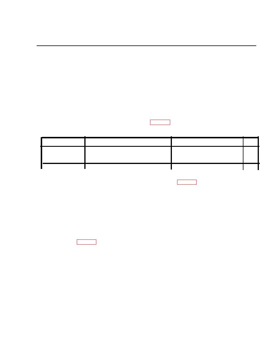
Table 4-1. Consumable Items
U/M
Identifying Part No.
NSN
Item
cn
Lubricant
MIL-S-8600
pk
Lens paper
NNN-P-40
Section
Il.
TROUBLESHOOTING
housing (para 4-7c. ). Test electrical circuitry as
4-5. Tests and Inspections
follows:
NOTE
Use a multimeter and read resistance across the
Step-by-step procedures for removing and
switch terminals with the switch in the ON, mo-
replacing aiming light components are in Sec-
mentary, and OFF positions. Resistance should
tion III of this chapter.
be zero with the switch in the ON and momen-
a. Visual/Mechanical Inspection. Observe the unit
tary positions, and infinite with the switch in the
for obvious mechanical damage such as deformed
OFF position. If these readings are obtained, the
mounting bracket, inoperative switch, scratched lens,
switch asssembly circuitry is verified as con-
broken or jammed azimuth or elevation adjusters,
tinuous.
parted battery cap strap, and other evidence of damage
(2) E/ectrica/ Circuit. Reinstall the batteries (para
or misuse which might indicate a need for repair.
4-7b. ). With the switch assembly removed, short
Replace as required (para 4-7). Conduct checkout of
the switch leads together.
replacement and check proper operation of the aiming
light. If operable, return to service. If not operable,
CAUTION
continue troubleshooting.
Do not allow either lead terminal to touch the
b. Continuity Checks.
aiming light housing when batteries are in-
stalled.
(1) Switch Assembly. Remove the batteries (para
Conduct a functional test (fig. 4-l). In a d2
4-7b. ). Remove the switch assembly from the
4-1


