TM 5-6675-250-20
2-8. ASSEMBLY AND PREPARATION FOR USE (Continued)
F I N E - L E V E L I NG
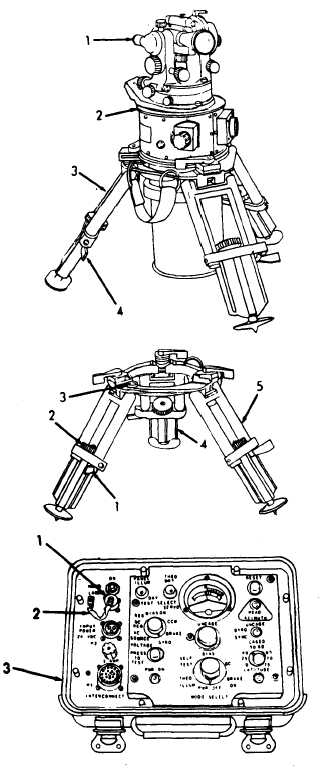
a . R o t a t e t h e o d o l i t e a l i d a d e ( 1 ) s o t h a t t h e
long axis of the plate level (2) is in the same plane
as one of the tripod legs (3).
b . A d j u s t f i n e - l e v e l c o n t r o l ( 4 ) t o p l a c e t h e
bubble in the center of the level vial.
N O TE
If adjustment cannot be made, proceed
to next step.
c. Release one of the tripod leg clamps (1).
d. Adjust leg (2) to obtain a level indication on
tripod circular level (3). Repeat procedure for each
of the other two tripod legs.
e.
R o t a t e t h e a l i d a d e 9 0 d e g r e e s a n d a d j u st
both the remaining legs (4 and 5). Continue the
p r o c e s s u n t i l t h e a l i d a d e c a n b e r o t a t e d 3 60
d e g r e e s w i t h n o m o r e t h a n ± 1 / 2 d i v i s i o n d i s-
placement of the bubble.
N I G H T O P E R A T I O N
N O T E
A h a n d - l a m p a s s e m b l y m a y b e u s ed
during night operations. A hand-lamp
switch and receptacle are provided on
ECU to accommodate the assembly.
a . R e m o v e c a p a n d c h a i n ( 1 ) f r o m h a n d l a mp
connector (2) on ECU case (3).
2-13


