TM 5-6675-250-20
2-8. ASSEMBLY AND PREPARATION FOR USE (Continued)
SETUP PROCEDURE WITH AUXILIARY TRIPOD (Continued)
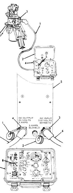
k. Connect the interconnect cable (1) between
the ECU (2) and GRU (3).
l . C o n n e c t p o w e r c a b l e ( 4 ) b e t w e e n t h e
POWER receptacle (5) on the ECU (2) and a 22-33
Vdc power source.
A C - D C C O N V E R T E R A S S E M B LY
N O TE
The AC-DC converter assembly
vialed to permit the surveying
is pro-
instru-
ment to be powered from a 115 Vat, 60
o r 4 0 0 H z p o w e r s o u r c e . W h e n c o n-
nected to the AC power source, the con-
v e r t e r s u p p l i e s t h e D C v o l t a g e
n e c e s s a r y t o o p e r a t e t h e i n s t r u m e n t .
The converter and interconnecting elec-
trical cables are stored in the transport
case. Cap assemblies are provided on
the converter to protect the electrical
receptacles when the equipment is not
in use.
a.
R e m o v e c o n v e r t e r a n d a s s o c i a t e d c a b l es
from the transport case when it is needed for use.
b . R e m o v e p r o t e c t i v e c a p s ( 1 a n d 2 ) f r o m
receptacles (3 and 4) on converter (5).
c. Connect the 115 Vac cable (6) between the
AC power source and input receptacle (3) on
converter (5).
d . C o n n e c t p o w e r c a b l e ( 7 ) b e t w e e n o u t p u t
receptacle (4) on converter (5) and power recep-
tacle (8) on ECU (9).
2-12


