Figure 2-182.
TM 5-3610-286-20
g.
Adjust.
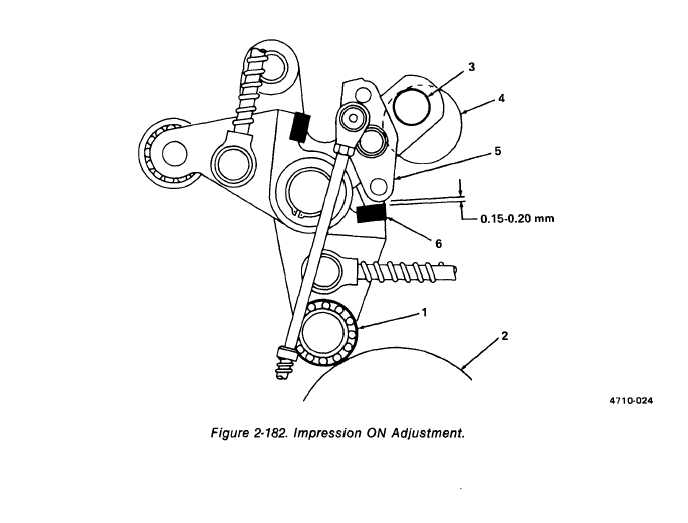
(1) Adjustment, impression ON, manual. (figure 2-182)
(a)
(b)
(c)
(d)
Using manual lever, put press in impression ON.
Inch press forward until roller (1) comes to a stop at the highest point of cam (2).
Check that bolt (3) contacts the upper run of the recess (4) in the side frame.
NOTE
If bolt does not contact upper run of recess, adjust engaging lever (D/S)
(para. 2-36).
Measure distance between pawl (5) and plate (6). Adjust to between 0.15 to 0.20 mm,
using shims if required.
2-381