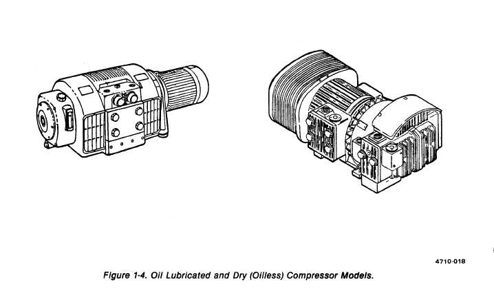
Figure 1-4.
TM 5-3610-286-20
1-8.
Location and Description of Major Components (cont).
(16) Electrical group (16).
(a) Main power box. Located at feeder end on drive side (D/S) of the printing press.
Contains relays, contractors, and other electrical components which supply electrical power to the
printing press.
(b) Electronic control box. Located under feeder tape table on the operator’s side (O/S) of
printing press. Controls operation of feeder and ranger drum by sensing signals sent from light
sensors.
(c) Main control box. Located on operator’s side (O/S) of feeder. Operator’s main control
station.
(d) Auxiliary control boxes. Mounted in several areas on printing press. Allow operator to
control specific printing press operations from those areas.
(17) Control register system (17). (figure 1-5) This plate punch is mounted on its own stand
(1) and is located in press section. A manually operated lever system (2) causes cutting tools (3) to
punch locating notches in a print plate (4) when correctly positioned on the control register easel
(5). These notches are used to aline plate with register scopes on printing press plate cylinder.
1-12

