TM 5-3610-286-20
d.
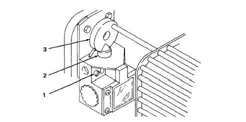
Aline. (figure 2-11)
NOTE
(1)
(2)
(3)
(4)
Safety limit switches on printing press open (or close) contacts after switch
plunger is depressed (or not depressed). Safety limit switch plunger travels 1
mm between opening and closing of contacts regardless of the type of actuator
or push rod that presses or releases the plunger. Mounting screws are the
same for all switches.
Loosen two screws (1),
Using feeler gage, aline plunger to allow 1 mm space between plunger (2) and push
rod (3).
Tighten two screws (1).
Recheck measurement with feeler gage.
Figure 2-11. Safety Limit Switch Alinement.
2-69