TM 5-3610-253-14
Remove socket head screws and fan from left side of cutter assembly.
q.
Remove shaped guide plate on left side of cutter assembly.
r.
Remove two hex head bolts from ends of cutter shafts; then reinstall
s.
them back into the shafts for three complete turns only.
t.
Remove eight hex head bolts at each corner of both wooden end plates
to remove inside and outside cutter shields and mounting frame.
u.
Tap left end plate around inside edge with hammer to remove.
v.
Remove two hex head bolts from ends of cutter shafts.
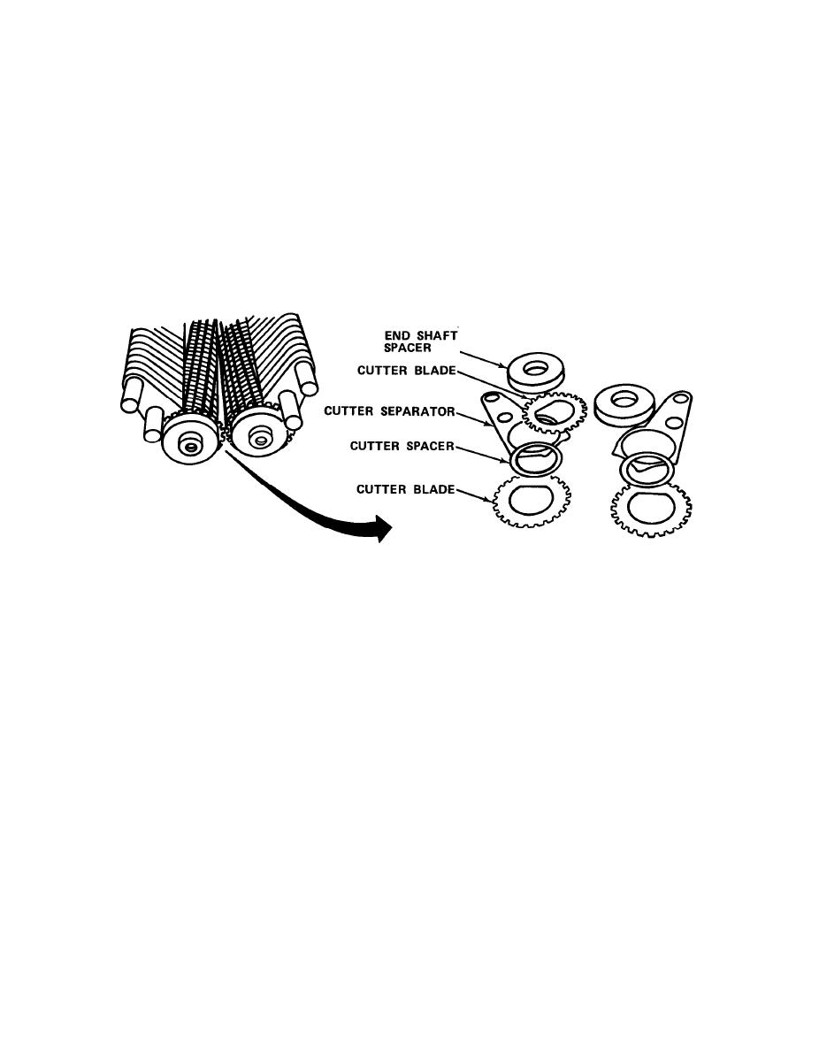
NOTE
Components are assembled on cutter shafts in the following order from
the bottom (right end): Cutter blade, cutter spacer, cutter separator.
w.
Examine each component of the cutter assembly for damage or wear,
and replace as necessary.
x.
Reinstall wooden end plate by tapping gently with hammer.
Reinstall two hex head bolts into ends of cutter shafts.
y.
z.
Reinstall inside and outside cutter shields and mounting frame, and
secure with hex head bolts.
aa. Reinstall drive motor and drive chain.
ab. Reinstall left shaped guide plate.
ac. Reinstall fan on left end of assembly and secure with socket head
screws.
4-44

