TM 5-3610-253-14
h. Remove relay mounting screws and move relay and cable aside.
i.
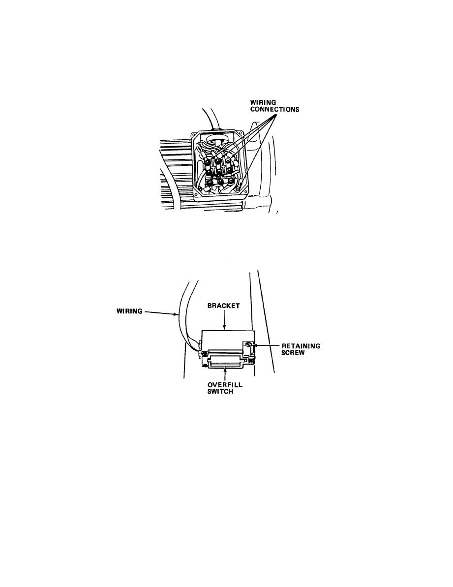
Remove screws and cover from junction box on drive motor.
Unscrew
plastic strain relief.
j.
Tag and remove four direction switch wires from the junction box.
Reinstall cover on junction box.
k. Remove screws attaching basket overfill switch behind cutter assembly.
Move switch aside.
Remove overfill indicating flap by lifting straight up.
l.
m.
Remove cutter assembly mounting bolts, lockwashers, and nuts.
4-42

