
TB 1-4920-443-35
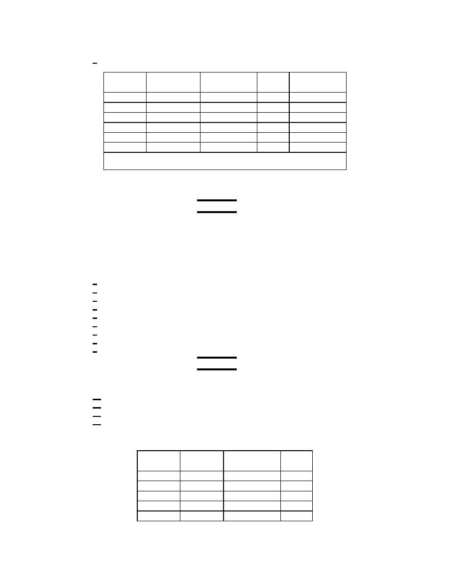
AEDATS IV T700 ALIGNMENT WORKSHEET
5
Channel 5 Connector P91 Pins B (+) M (-)
Output(mAvg)
(Vert. Scale)
(Limits)
AEDATS 4
Meter
(V5)
____________
____________
Shorted
100hz
116.5
____________
.9-1.1
____________
100hz
233.0
____________
1.9-2.1
____________
100hz
350.0
____________
2.9-3.1
____________
100hz
466.0
____________
3.9-4.1
____________
100hz
583.0
____________
4.9-5.1
____________
Transducer: T74
Hardware Name: HL30
(12)Vibration system (vibration Test # 2)
NOTE
2700 Calibration box has an internal switch, it must be in the ON position.
Calibration lab may leave switch in the OFF position
(a) Use J1 with red cable (CEC-619566-120) and T700 engine vibration cable to drive the charge
amps.
(b) Connect test box CEC 2700 (J1) to the inputs of the vibration cables.
(c) Set channels 1, 2, and 3 meters as follows:
1 Filter switch to CAL
2 Range switch to 150
3 Xducer switch to ACC
4 Mode switch to VEL
5 Output switch to AVG
6 Variable filter Out
7 Adjust Cal pot for a reading of 50 on Ch2. and 10 on Ch. 1 and 3.
8 Set filter sw to SENS
9 Adjust SENS pot for a reading of 150/75 on the digital display of channels 1, 2, and 3.
NOTE
(75 only applies to sites with the Endevco system installed)
Set XDUCER switch to VEL
10
Set OUTPUT sw to RMS.
11
Range 5
12
Filter OUT
13
(d) Channel 1 Connector J26 ( V1) (charge amp box)
Output
(Vert. Scale)
(Limits)
(Pcmb/mv)
Meter
100hz
16.3
____________
.9-1.1
100hz
32.5
____________
1.9-2.1
100hz
48.8
____________
2.9-3.1
100hz
65.1
____________
3.9-4.1
100hz
81.4
____________
4.9-5.1
165
