
TB 1-4920-443-35
AEDATS IV T700 ALIGNMENT WORKSHEET
6. AEDATS IV T700 Alignment Worksheet
NOTE
Ensure system is in the T700 mode
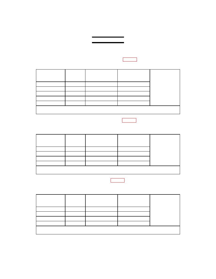
(1) Angle Position Measurement System
(a) Dyno shroud Position Indicator
(Refer to page 78 step 59)
(b) Input the following voltages into connector P91 pins F+ and H-.
Vertical Scale
Input Voltage
Percent
AEDATS 4
Vertical Scale
Bottom row 3
Reading
(DynoShrd)
+/-.1%
+/-.5%
0 volts
0%
____________
____________
4 volts
25%
____________
____________
8 volts
50%
____________
____________
12 volts
75%
____________
____________
16 volts
100%
____________
____________
Transducer: T76
Hardware Name: HL33
(2) Load Demand Spindle Position
(Refer to page 79 step 60)
(a) Input the following voltages into connector P51 pins A(+) and B(-). Connector P51 at Engine
(LDS)
Vertical Scale
Input Voltage
Degrees
AEDATS 4
Vertical Scale
Bottom row 2
(LDS)
+/- 1.0 deg
+/- .5 deg
0 volts
-45
____________
____________
4 volts
05
____________
____________
8 volts
55
____________
____________
12 volts
105
____________
____________
Transducer: T82
Hardware Name: HL35
(a) Input the following voltages into connector P50 pins A(+) and B(-).Connector P50 at Engine
(PAS)
Vertical Scale
Input Voltage
Degrees
AEDATS 4
Vertical Scale
Bottom row 1
(PAS)
+/- 1.0 deg
+/- .5 deg
0 volts
0
____________
____________
4 volts
50
____________
____________
8 volts
100
____________
____________
12 volts
150
____________
____________
Transducer: T78
Hardware Name: HL34
153
