
TB 1-4920-443-35
AEDATS II T53 ALIGNMENT WORKSHEET
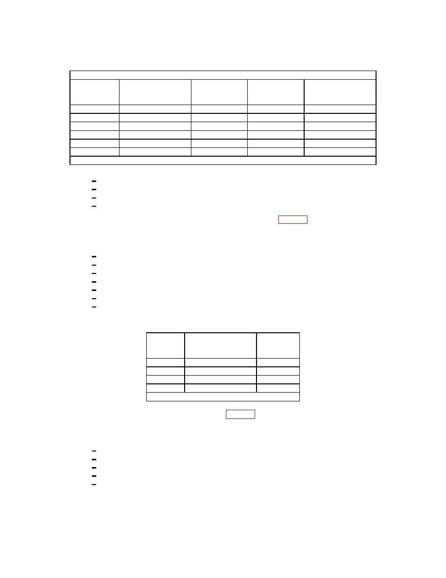
(l) Input the following frequencies into TB 201 pins 1 (+) and 2 (-).
Note: Cell constant Low K Factor (#3)
Oscillator Hz
Calculating Counter
AEDATS 2
Calculating Counter
+/- 1 Hz
Sheet Hz
PPH+/- .35 %
(WF1)
+/- 1 Hz
0Hz
____________
____________ ____________
____________
600Hz
____________
____________ ____________
____________
800Hz
____________
____________ ____________
____________
1000Hz
____________
____________ ____________
____________
1200Hz
____________
____________ ____________
____________
1400Hz
____________
____________ ____________
____________
(Note: frequency x C = PPH) (CH 4C= 3600 x 8.337 x SG /K factor)
K- Factor = Hz. x Time base / Flow rate
1
PPH= GPM x 500 x SG. Or GPM= PPH/500xS.G.
2
PPH= Pulses per second (Hz). x 3600 x S. G. x 8.347 / pulses per gallon ( K Factor)
3
Correction Factor 78 x 8.337 x SG / 2000
4
(10)Oil flow measurement CEC 2700 BOX T53/T63
(Refer to page 20 step 24)
(a) Ensure the system is in the T53/T63 test mode, with the correct flight harness connected to the J-
box.
(b) Set calculating counter controls as follows: (Channel 3)
1 DEC
6
2 C
01000
3 10n
0
4 Auto
depressed
5 X10
depressed
6 Sample Rate (fast)
1
7 Test
released
(c) At the Large Engine Test Trailer, disconnect the cable from the T53/T63 Oil Flowmeter. Connect
the CEC 2700 oscillator to pins A and B of the cable connector.
Oscillator
Calculating Counter
AEDATS 2
(Hz)
+/-1 Hz
(WF2)
(Hz)
300
600
900
1300
Note: frequency x C = PPH
(11)Vibration system, T-53/55/63
(Refer to page 14 step 18)
(a) Set variable filter channel switches to 2, on channels 1, 2 and 3 filter selector switch to out, and
power switch to on.
(b) Set all meters as follows:
1 Filter switch to
CAL
2 Range switch to
150
3 Xducer to
ACC
4 Mode switch to
ACC
5 Output switch to
AVG
(c) Adjust cal pot to 105 on digital display on all channels
(d) Set filter switch to sensitivity and adjust sens pot for an indication of 150 on all channels
126
