TB 1-4920-443-35
68. T53/T55/T63/T64 Test Trailer - Dynolube Gauge (Optional)
(1) Supply Gauge (0-100 PSI)
(a) Locate the Dynolube Supply gauge on the Dynolube Control Panel. Remove the plumbed line on
the back of the gauge. Connect the High Pressure Calibrator and set and record the following
points:
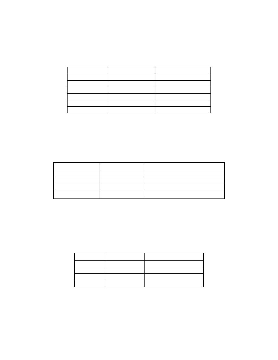
Table 68-1 Supply Gauge Alignment
Set Point (psig)
Measured Value
Limits
0 (Vent)
-3 to 3 psig
20
17 - 23 psig
40
37 - 43 psig
60
57 - 63 psig
80
77 - 83 psig
100
97 - 102 psig
(b) Remove the test equipment. Reconnect the plumbing removed in step 1 above. Leak check this
connection.
(2) Scavenge Gauge (-30" Hg to +15 PSIG)
(a) Locate the Dynolube Scavenge gauge on the Dynolube Control Panel. Remove the plumbed line
on the back of the gauge. Connect the Low Pressure Calibrator to a "T" line. Connect the Vacuum
pump and the gauge to the remaining ports on the "T" line. Set and record the following points.
Table 68-2 Scavenge Gauge Alignment
Set Point
Measured Value
Limits
0 (Vent)
-0.5 to 0.5"Hg (-.25 to +.25 PSI)
-5"Hg (-2.46PSI)
-4.5 to -5.5"Hg (-2.21 to -2.70 PSI)
-10"Hg (-4.91PSI)
-9.5 to -10.5"Hg (-4.67 to -5.16 PSI)
-15"Hg (-7.37PSI)
-14.5 to 15.5"Hg (-7.12 to -7.61 PSI)
(3) Remove the test equipment. Reconnect the plumbing removed in step 1 above. Leak check this
connection.
(4) Large Test Trailer Oil System Gauge (Optional)
(a) Locate the 0-15 PSI gauge on the Oil System Disconnect Panel on the Large Test Trailer.
Remove the plumbed line from the back of this gauge.
(b) Connect the High Pressure Calibrator to the gauge, set and record the following points:
Table 68-3. Large Test Trailer Oil System Gauge Alignment
Set Point
Measure Value
Limits
0 (Vent)
-.75 to .75 psig
5 psig
4.25 to 5.75 psig
10 psig
9.25 to 10.75 psig
15 psig
14.25 to 15.75 psig

