TM 9-4931-436-14&P
Alignment Device,
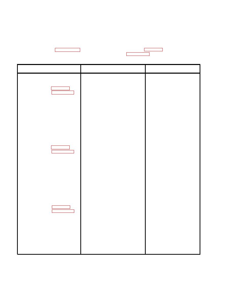
Direct Support Troubleshooting Table
Table 5-1.
NOTE
Before you use this table be sure you have performed all normal operational
checks. Use figure 5-1 for electrical tests. Refer to chapter 6 for re-
moval and replacement instructions. Refer to chapter 7 for test instructions.
TEST OR INSPECTION
CORRECTIVE
ACTION
MALFUNCTION
1. Inspect for broken wire.
1. Repair or replace
VOLTAGE METER FAILS TO
1.
harness assembly W10
READ
2. Inspect for loose
2. Tighten or replace
(Refer to fig. 5-2,
connector.
connector.
retest per chapter 7)
3. Inspect for bad solder
3. Resolder connection.
connection.
4. Test for defective
4. Replace defective
meter.
meter.
5. Test for defective
5. Replace PWB A3.
regulator board A3.
6. Replace regulator
6. Test for power at input
board.
and output on regulator
board.
1. Inspect and test
1. Replace batteries.
VOLTAGE METER READS
2.
batteries.
INCORRECTLY
2. Inspect for broken wire.
2. Repair or replace
(Refer to fig. 5-2,
wiring/harness
retest per chapter 7)
assembly W1O.
3. Resolder connection.
3. Inspect for bad solder
connection.
4. Test for defective Ml.
4. Replace Ml.
5. Test for defective
5. Replace A3.
regulator board A3 by
substitution.
1. Press BATTERY CHECK
1. Go to MALFUNCTION
DISPLAYS DO NOT APPEAR
3.
WITHIN ONE SECOND WHEN
pushbutton and verify
No. 1.
DEVICE INITIALLY
voltage is 13 to 18
TURNED ON.
volts.
2. Replace battery
2. Test battery contacts.
(Refer to fig. 5-2,
contacts.
retest per chapter 7)
3. Replace A3.
3. Test for power on regu-
lator board A3 at input
and output.
4. Test logic boards A2A2,
4. Replace defective
board
A2A3, and A2A4 by
substitution.
5. Test continuity between
5. Repair or replace
wiring/harness
S2 and regulator board
assembly W1O.
A3.
5-2


