TM5-6675-326-14
2-14.1 Replace ON/OFF Switch - Continued
NOTE
Wiring is connected to cover and switches.
d.
Tag wires and desolder from ON/OFF
INSTALLATION:
a. Solder wires to new ON/OFF switch.
s w i t c h .
Remove tags.
b.
Install new ON/OFF switch and secure with bezel nut.
NOTE
Make sure that wires are not loose, crossed, or
disconnected before securing cover.
Green
(ground) wire is connected to cover screw.
c .
Reinstall cover and secure with four socket-head screws.
d .
Plug in power cord, and turn power ON.
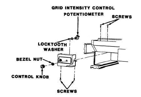
2-14.2 Replace Grid Intensity Control Potentiometer
PERSONNEL REQUIRED:
1 Topographic instrument repair s p e c i a l i s t M O S 4 1B
TOOLS:
7/64-in. socket-head screw key
1/2-in. socket-head screw key
1/2-in. combination box and open end wrench
Soldering gun
MATERIALS/PARTS: Potentiometer
Solder, item 87, appendix E
2-43