
TM 5-6675-323-14
Section II OPERATING INSTRUCTIONS
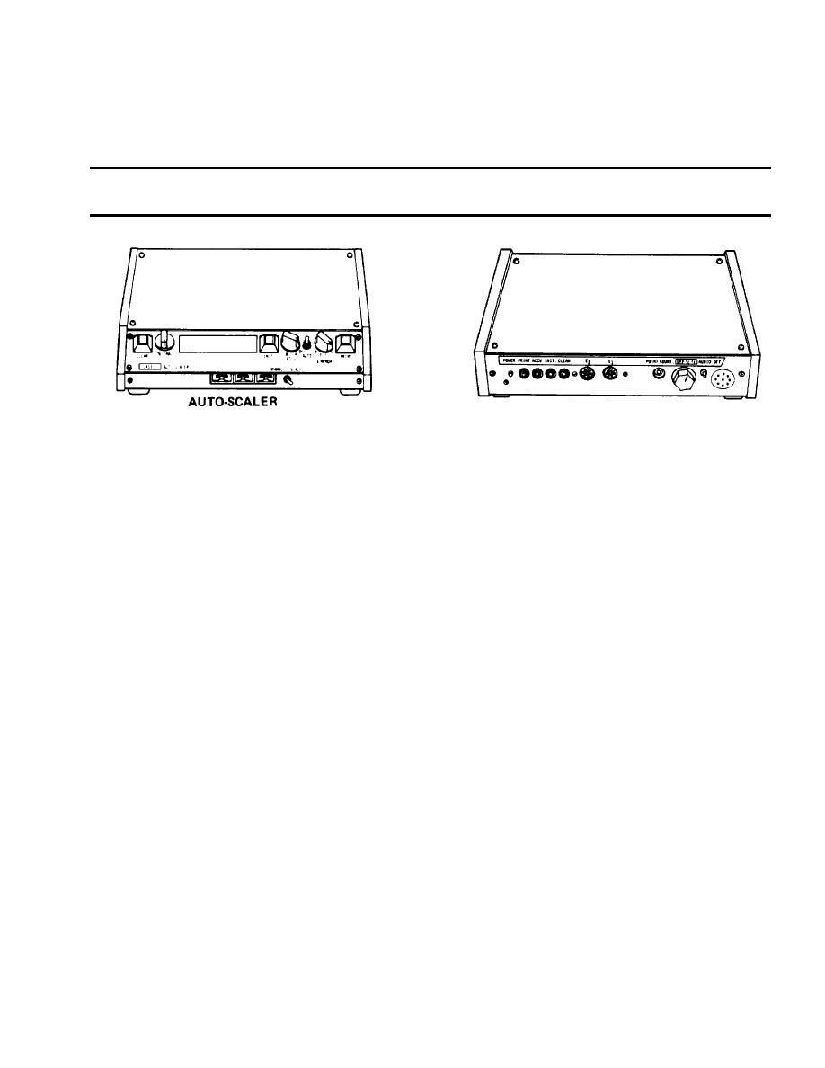
Key
Control or Indicator
Function
CLEAR button
Clears all displays and
memories.
DECIMAL switch
Selects position of
decimal point in auto-
scaler display.
LED indicator light
I n d i c a t e s when pulse
count is positive,
L E D display
Displays current pulse
count total.
SCALE dials
Inputs three most signi-
ficant figures of constant
into scaler.
NORMAL/SCALE
In NORMAL, pulse count
is not scaled.
I n SCALE, activates in-
ternal scaling circuit.
INIT button
S e n d s initialize command
signal to calculator.
