TM 5-6675-323-14
(5) Remove four screws and front bottom panel.
(6)
R e m o v e four screws and front panel assembly.
(7)
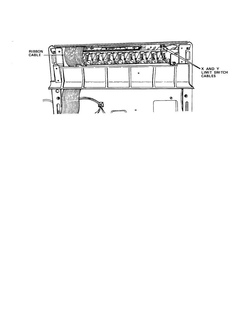
T a g and unplug X-and Y-limit switch cables from PCA A3.
(8)
U n p l u g ribbon cable from PCA A3.
(9)
Remove two screws and capper assembly.
(10)
Remove seven screws and defective PCA A3 board.
(11)
Install new A3 board and secure with seven screws.
Reinstall capper assembly and secure with two screws.
(12)
(13)
P l u g ribbon cable into new PCA A3.
(14)
Plug in X-and Y-limit switches.
(15)
Reinstall front panel assembly and secure with four screws.
(16)
Reinstall bottom panel and secure with four screws.
Reattach upper deck assembly to plotter.
(17)
(18)
Reconnect ground cable on forward line switch brackets.
R e c o n n e c t motor cables and front panel cables to PCA A2.
(19)
Plug pen solenoid cable and platen cable into PCA A6.
(20)
3-273

