TM 5-6675-316-14
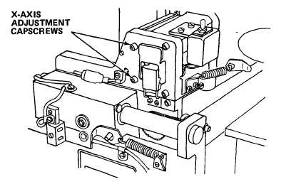
b. Loosen capscrews securing X-rail to end support plates. Tighten
lower, rear screws at each end.
Three other screws on each end should
be snug.
c.
Fold piece of thick paper over right-hand, rear, upper edge of X-rail to
protect surface.
Fit wrench over protected section of X-rail.
d. Move optical mount to right-hand stop.
Move carriage between front and
rear stops.
Check collimation.
e.
If collimation is outside + 5 minutes of arc, use wrench to turn X-rail
to bring collimation within limits.
Tighten upper front attaching
screw on X-rail support plate on right-hand end securely.
f. Move optical mount to left-hand stop, and repeat procedure for left-hand
end of carriage assembly.
9.
Check Y-axis collimation at point near center of table. Readjust X-
rail, if necessary.
h. Tighten all four attaching screws on both X-rail support plates, and
recheck collimation in Y-axis.
i.
Move carriage assembly so that autocollimator mirror is near rear end of
stage glass.
Move optical mount between left-hand and right-hand limits
while checking collimation.
j.
Move carriage assembly so that autocollimator mirror is near front end
of stage glass.
Move optical mount between left-hand and right-hand
limits while checking collimation.
4-78