6-14
ARMY TM 5-6675-238-14
MARINE CORPS TM 08839A-14/1
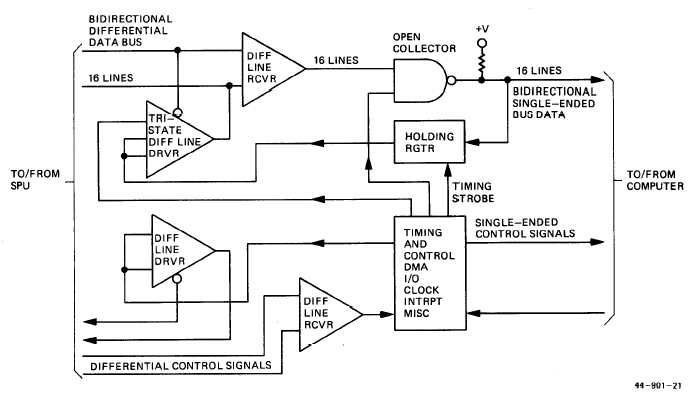
Figure 6-4. Buffer Unit Functional Block Diagram
transistor turns on, which causes the output transistor
to be turned off, producing an output voltage level
greater than +3.5V. For darkened inputs (no hole), the
input transistor is turned off causing the output transis-
tor to produce a voltage output of less than 0.8 VDE,
The light level at which the photocell amplifier
switches from off to on is determined by the setting of
the input bias potentiometer for each amplifier input.
The amplifier outputs are parallel transferred via con-
nector J2 to external using equipment. Amplifier out-
puts are also made available at test points located on
terminal board TB1.
c. Drive System and Control. The tape drive con-
trol system consists of pulse rate generator and logic
plug-in circuit card, forward/reverse control plug-in
circuit card, and two motor driver control plug-in
circuit cards used for drive and control of step motor
Bl. Also included is servo amplifier plug-in circuit card
which accepts constantly varying DC inputs for bidirec-
tional tape spooling control of spooling motors B2 and
B3. Spooling disable is provided by a switch mounted
on the front panel, This switch removes the +28V
from all internal circuits, disabling the spooling and
stopping functions. This allows removal and installation
of the tape while external power is applied to the tape
reader.
d. Step/Run Control. When a step command is
applied to the pulse rate generator and logic plug-in
circuit card, a negative-going output step trigger is
generated. This action continues at the external step
rate, provided the run input is at 0V. The step trigger is
applied to both motor driver control plug-in circuit
cards. In addition, a reverse signal is developed and
imported to the forward/reverse control plug-in circuit
card. When the external forward input control signal is
at 0V, the output signal levels of the forward/reverse
control logic are the same as the input, and the forward
sequencing condition exists, When the input control
signal is at + 5V, the output signal levels are inverted
and the reverse sequencing condition exists. The alter-
nating output levels are applied to the set and clear
inputs of the flip-flops on each motor driver card, The
flip-flops are constrained by the input gating action and
provide the correct sequence of output pulses to step
the stepping motor in the forward direction (counter-
clockwise sprocket rotation) or in the reverse direction.
The flip-flop output from each motor driver card and
the step trigger pulse provide control and drive to
motor driver output circuits, The motor driver outputs
are connected to the windings of step motor Bl.
e. Forward/Reverse Control. In the forward mode
of operation, power is applied to servo feedback poten-
tiometers R2 and R3 in a direction to supply a servo
drive input voltage to an associated servo amplifier
circuit on servo amplifier plug-in circuit card. The
input is proportional to the amount of tape on the reels
as controlled by the movement of each tape sensing


