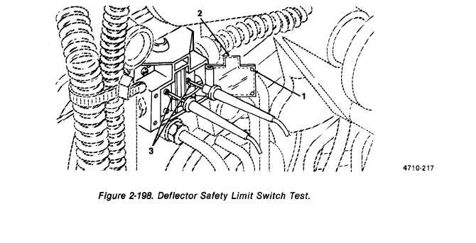
Figure 2-198.
TM 5-3610-286-20
2-74.
Deflector Safety Limit Switch.
This task covers:
a. Test
b. Replace
c. Aline
INITIAL SETUP
Tools
Equipment Coalitions
1 mm feeler gage
Upper guard (O/S) removed (para. 2-18)
Muitimeter
0,050 x 0.375 x 8 in. flat-tip screwdriver
Additional Personnel Requirement
No. 2 x 4 in. cross-tip screwdriver
Electrician MOS 35E20
a. Test. (figure 2-198)
NOTE
Some switches are wired into the same circuit, for example, upper and lower
limit switches. Refer to table 2-5, Troubleshooting, to determine switch to be
tested.
(1) Loosen two screws (1) and open hinged cover (2).
(2) Set muitimeter to 0 ohms scale.
(3) Test for continuity (para. 2-16) at terminals (3).
(4) If no continuity (in either plunger position), replace switch.
2-406

