TM 11-5855-261-23
CAUTION
(13) Place the switch leads inside the laser diode
Separate connector plate evenly to avoid ben-
cavity. Place the index finger of your left hand into
ding pins.
the laser diode cavity (fig. 4-6) and the index finger
j. Replacement of Electronics, Laser Diode, and
of your right hand into the electronics assembly
Diode Carrier Assemblies.
cavity. Pull with your left finger and push with
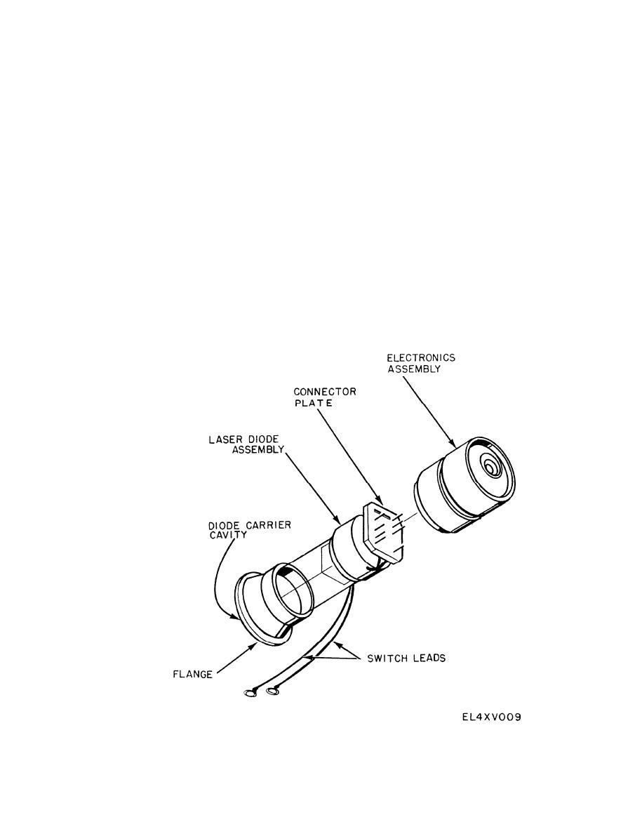
(1) Assemble the laser diode and electronic as-
your right finger to remove the combined assemblies.
semblies (fig. 4-7). Insert the connector plate into
CAUTION
the electronic assembly with care to avoid bending
Pull the combined laser diode and electronic
pins. Observe keying arrangement of pins and
assemblies from the housing.
sockets. Gently fold the electronic assembly over in
NOTE
line with the laser diode assembly.
The butt end of a screwdriver may be used to
(2) Inspect the O-rings for the electronic assembly
assist in pushing the combined assemblies out
and refractive lens assembly and clean or replace
if required.
as required. Lightly lubricate (MIL-S-8660, or
NOTE
equivalent) and seat the O-rings.
The flange on the forward (diode carrier) end
CAUTION
of the laser diode assembly may catch in the
Place switch leads inside diode carrier cavity of
lens O-ring groove or threads. It may be freed
the laser diode assembly before proceeding, to
by gently wiggling the laser diode assembly.
avoid crimping leads when inserting assemblies.
(14) Separate the laser diode and electronic assem-
(3) Carefully insert the electronic assembly, with
blies. A flat screwdriver may be used to carefully
the laser diode assembly attached, into the scatter-
pry the connector plate loose.
Figure 4-6. Electronic assembly, laser diode carrier assembly.
4-8


