
ARMY TM 9-1290-262-24&P
MARINE CORPS TM 00476C-24&P
AIR FORCE TO 49A7-3-72/74
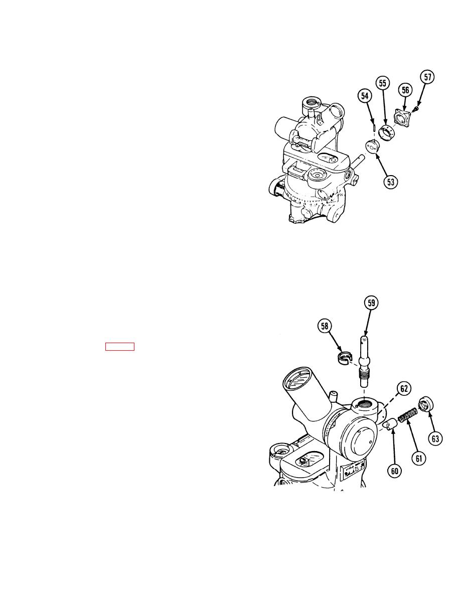
Install flat washer (52) and adapter (53) on
52
worm shaft (44). Aline adapter pin hole
with pin hole in shaft and install taper pin
(54).
NOTE
If a new worm was installed, perform
steps 53 thru 55 as follows:
Position scale dial (55) over adapter (53)
53
and push toward azimuth index (51).
Leave a clearance of no more than 0.015
in. (0.381 mm) between scale dial and
azimuth index.
Remove scale (55), but do not move
54
adapter (53).
Using hole in adapter (53) as a guide, drill
55
a No. 52 hole in worm shaft and ream for
No. 6/0 pin. Install pin (54).
Install scale dial (55), knob (56), and two
56
screws (57). Do not tighten screws until.
after collimation adjustment.
Lightly lubricate ball socket seat (58),
57
worm shaft (59), sleeve bushing (60),
spring (61), and all bearing and working
surfaces inside body assembly with grease
(item 6, appx D).
Place ball socket seat (58) on worm side
58
of ball, alining slot in ball socket seat with
setscrew hole in housing.
To install worm shaft (59) in body assem-
59
bly, push in and rotate worm onto internal
gear until ball socket seat (58) is in place
within body assembly.
Check that slot in ball socket seat (58) is
60
still alined with setscrew hole in body as-
sembly.
NOTE
Setscrew (62) will be tightened during
backlash adjustments.
Install sleeve bushing (60), spring (61),
61
and machine thread plug (63). Tighten
machine thread plug (63) securely.
3-23
