TM 5-6675-330-12&P
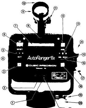
[b] Using OFFSET switches (5), dial the offset
correction into the instrument.
4. Test
An automatic test function is built into the
instrument, The test provides a quick check of the
internal microcomputer and display circuits, To
perform a test, proceed as follows:
(a] Press PWR switch (3) to turn on the instrument.
(b] When power is turned ON the instrument enters
the test mode, and the numerical display (7)
should sequence automatically from all zeros to all
nines and then display four zeros.
5. Target Acquisition
NOTE:
Maximum range accuracy can be achieved only
if the instrument is positioned accurately on target.
After the test function has been completed, the
instrument is ready for alignment on the retro-
reflector target. Using the vertical (17) and
horizontal (20) tangent screws, position the sighting
scope reticle on the target. For shorter distances
Figure 6- Controls
w
f? U.S. GOVERNMENT PRINTING OFFICE lSSS-SS4.1WS716
14
Change 1