TM 5-6675-325-14
e.
f.
g.
h.
i.
j.
k.
1.
m.
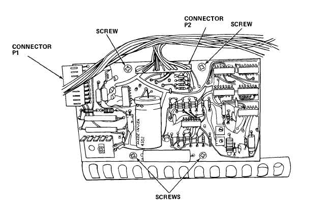
Unplug connector P2 by pulling straight out.
Unplug connector P1 by pulling to left.
Remove screws and defective board.
Install new board and secure with screws.
Reconnect P1 and P2 connectors.
Reinstall logic board cover.
Reinstall rear panel and secure with screws.
Reinstall rear paper loading door.
Plug in power cord.
3-98