TM 5-6675-325-14
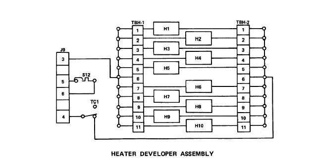
(4) During three to four minute warm-up cycle, two switches in the heater
developer assembly remain closed:
Temperature control thermostat TC1 remains closed
to apply line voltage to the heaters until the temperature reaches 277°F (136° C).
Temperature sensing switch S12 remains closed until temperature reaches 260° F
(127° C).
This stops movement of the main viewing mirror assembly and start of a
print cycle before the heater developer assembly reaches the correct temperature.
(5) The logic board is the control center for the reader-printer and deter-
mines that all conditions are met before allowing a print cycle to begin. This
board also checks that the heater developer assembly is at the correct temperature,
controls the mirror and paper drive motors, times the exposure lamp, and senses the
paper length selected.
Before the PRINT switch can start a print cycle, the logic
board must receive a high signal from the following components:
(a) Temperature sensing switch S12.
(b) Optical sensors 0S1 and 0S2.
With no paper blocking light from the
light-emitting diode (LED) to optical sensors, they produce a high signal at TP5 on
the logic board.
(c) The main viewing mirror inside cam. This cam holds contacts of
mirror home switch S1O open, and this gives a high signal at TP7 on the logic board.
(d) The main viewing mirror outside cam. This cam holds contacts of
mirror forward switch S11 open, and this gives a high signal at TP9 on the logic
board.
3-11