4-20.7
TM 5-6675-316-14
e .
Tag and desolder wires from switch.
f.
Solder wires to new carriage clutch.
9“
Insert carriage clutch switch through hole in cover and secure with nut.
h.
Reinstall cover, and secure with screws.
i.
Plug in power cord, and turn power on.
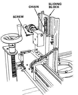
Adjust Z-Axis Chain.
MOS:
41B, Topographic Instrument Repair Specialist
TOOLS:
9/64 in. Flat Tip Screwdriver
a.
Turn power off, and set carriage clutch switch OFF.
b.
Lift optical ring assembly to point at least 2-1/2 in. (6.35 cm)
above lower limit.
c.
Loosen screws.
d.
Pull sliding block upward to tighten chain.
e.
Tighten screws to hold adjustment.
4-67