
TM 5-6675-316-14
(d) The 0.04 ohm resistors are printed circuit-type and are located under
the heat sink extrusion. For current limiting, the voltage between the collector of
pass transistor Q1 and the +5 V output terminal is sensed. This sets a bias voltage
on regulator U1, pin 2 with respect to U1, pin 3.
(e) Trimmer Rll is adjusted so that there is 650 mV between pins 2 and 3
when the output current is at the desired maximum. If the output load is increased,
then the voltage will decrease and the output current will also fall. With a full
short-circuit across the output, the current will be about 30 percent of the maxi-
mum. Resistors R6 and R14 are provided for protection in the event of a break in
one of the sense lines. They limit the output voltage to a level which will not
damage the external system. With both sense lines disconnected, the output voltage
will be approximately 1 V above set value.
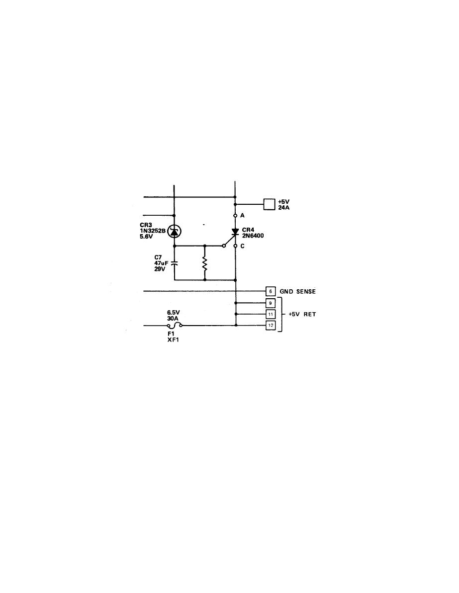
(f) Should a major failure occur, the full unregulated voltage (+10 V)
will attempt to reach the output terminals. At approximately +5.6 V, zener diode
CR3 will conduct current to the gate of SCR-CR4 and trigger it. This shorts the
output terminals, and blows fuse F1 as the current-limiting circuit is ineffective
in this situation.
2-72
