
TM 5-6675-316-14
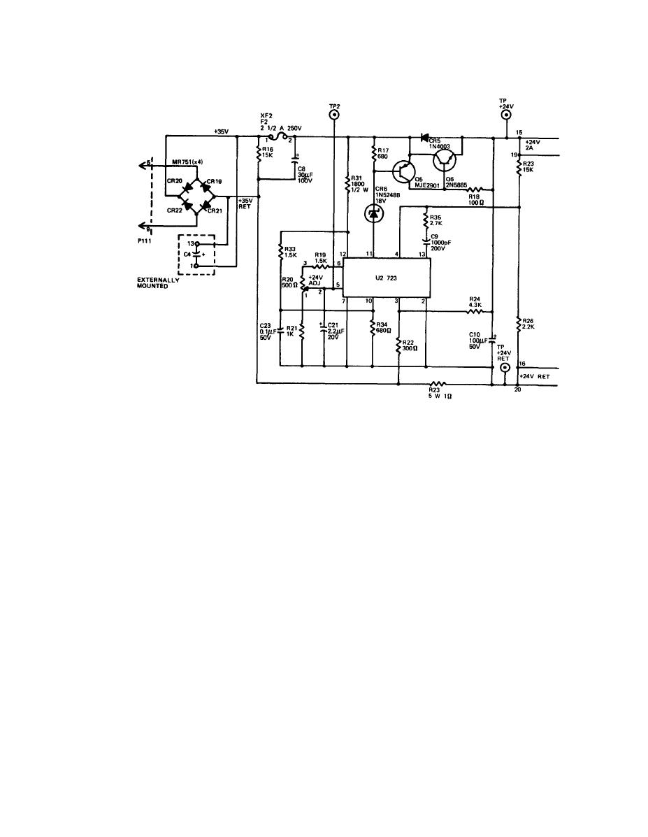
(3) +24 V circuitry. The +24 V circuitry is similar in configuration to the
+5 V supply but it supplies less current and has no overvoltage protection.
(a) The ac is supplied by a 27 V secondary winding on the main power
transformer and is rectified by bridge rectifiers CR19, 20, 21 and 22. Filtering is
provided by C4, which is mounted remote from the main board.
(b) The unregulated voltage is divided by R31, R33 and R34. This powers
regulator U2.
(c) Reference voltage is provided at pin 6 from voltage dividers R19, R20
and R21. Trimmer R20 provides a range from +2.4 to +3.6 V on pin 5. The output
voltage then equals ER2O (ER25 + ER26)/ER26. With the output voltage set to +24 V,
pin 5 voltage is about +3.1 V.
(d) Pin 11 seeks a current proportional to the output demand. This cur-
rent flows to ground through pin 10 and R34 and is sensed by the base of Q5, which
drives the base of emitter-follower 06. Resistors R22 and R24 bias pin 3 so that
with 650 mV between pins 2 and 3, the output current is 2.4 amps. Any increase in
output load will cause the output current to be limited. A direct short will result
in only 650 mA at the output.
2-73
